How Do You Measure DC-Link Capacitor Ripple Current in an Inverter?
Measure current in the capacitor branch under real inverter load, capture RMS and frequency content, then compare with the exact COREVIA series conditions.
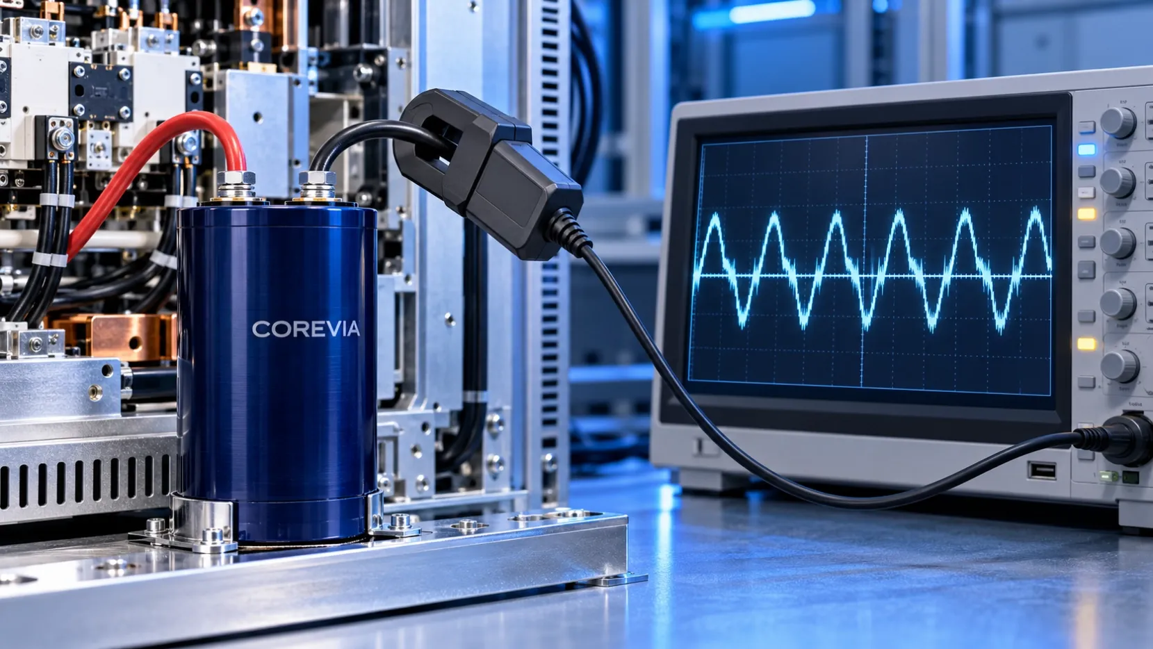
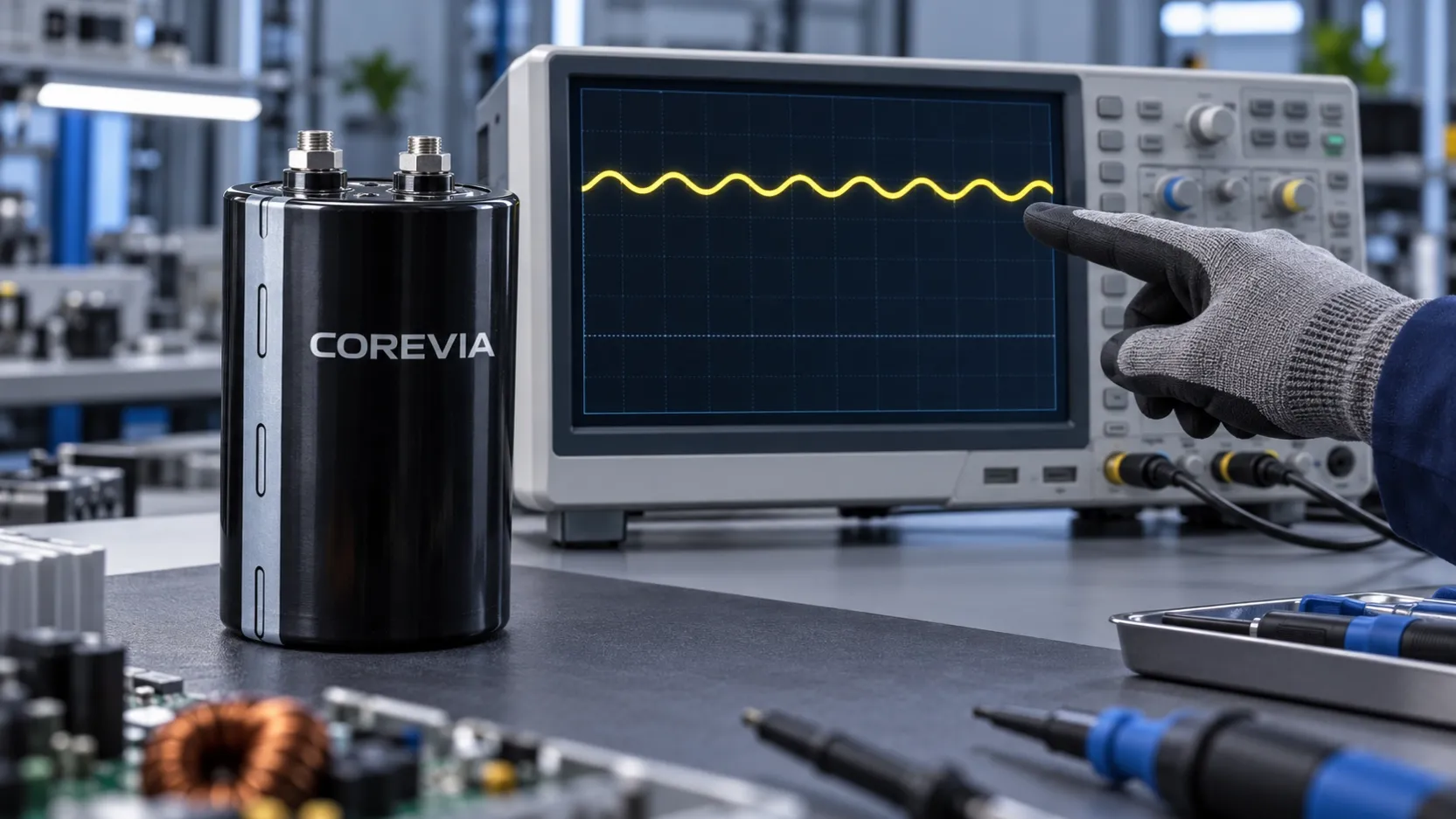
Measure the current flowing through the capacitor branch, not just the DC-bus voltage or total inverter input current. Under representative operating conditions, a qualified engineer should capture the branch-current waveform with a suitable current probe, determine its AC RMS value and frequency components, and compare the result with the exact COREVIA series rating at the applicable temperature and reference frequency.
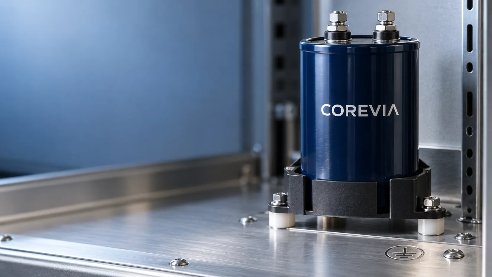
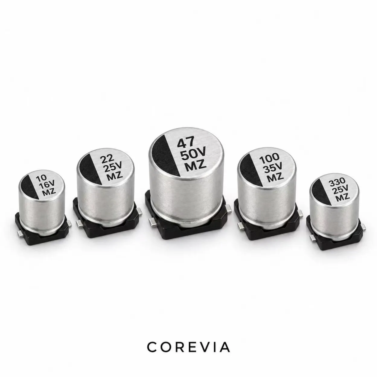
This matters when an inverter passes a voltage check but its DC-link capacitors still run hot. Bus voltage alone does not reveal how much alternating current is flowing through each capacitor. COREVIA offers screw-terminal and snap-in aluminum electrolytic capacitor families for power electronics; the specific part number, layout and load profile determine the meaningful comparison.
Choose the right measurement point
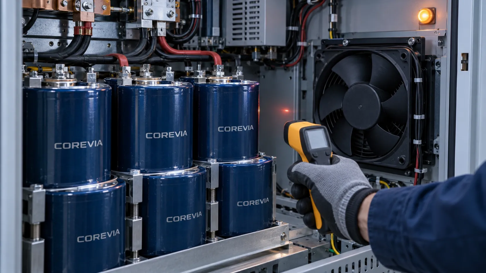
Place the current sensor around one conductor that carries the current of the capacitor or capacitor branch being evaluated. A probe around both outgoing and return conductors can cancel their magnetic fields, while a probe on a common busbar measures a different current. In a parallel bank, a bank-total reading does not prove that every capacitor shares ripple equally.
Plan the measurement before energizing the cabinet. Use equipment rated for the circuit and an approved safe-access procedure. If a temporary conductor or probe clearance would change the busbar geometry, document that alteration because it may change the current distribution. Avoid treating an easy-to-reach point as equivalent to the capacitor terminal without checking the schematic.
| Measurement | What it answers | What it cannot establish alone |
|---|---|---|
| DC-bus voltage waveform | The voltage seen by the bank | Current in one capacitor branch |
| Common busbar current | Total current at that location | Ripple sharing among parallel parts |
| Single capacitor branch current | Waveform and AC RMS load for that path | Allowable rating without series and temperature data |
| Local temperature | Installed thermal condition | Current spectrum or junction temperature by itself |
Capture the duty cycle and frequency content
Record the inverter state, load, DC-bus voltage and local temperature with the current waveform. Include steady load and the operating states that could produce higher ripple. For a variable-speed drive, a single no-load screenshot is a poor substitute for the actual duty cycle.
The relevant ripple quantity is the RMS value of the alternating component. A waveform can contain both low-frequency rectifier ripple and higher-frequency switching components. An oscilloscope with suitable current-probe bandwidth and spectrum analysis can separate those components; capture enough complete cycles of the slow component to avoid misleading spectral results. Check probe zero, bandwidth and acquisition settings before using the numbers for selection.
Do not add frequency-component RMS values arithmetically and call the result a measured RMS current. The comparison method and any frequency correction must come from the exact capacitor series documentation. The ripple-rating comparison guide explains why reference conditions matter; this article concerns how to obtain the application current first.
Turn the measurement into a COREVIA selection review
Send the full part number and its data sheet revision with the recorded branch-current waveform or spectrum, AC RMS result, operating frequency components, load states and measured local temperature. Identify whether the reading is for one capacitor or the entire bank. Also send the busbar layout and the locations of the current probe and temperature sensor.
There is no universal measured-current pass threshold for all COREVIA parts. Check the selected series' ripple-current limit, reference frequency, temperature conditions and any applicable correction method. If a bank is involved, assess each branch rather than assuming equal sharing; see why one capacitor in a parallel bank may run hotter.
FAQ
Can I use DC-bus voltage ripple to calculate capacitor ripple current?
Not reliably from voltage alone in a real inverter. Circuit impedance, switching behavior and parallel paths affect the current. Measure the relevant branch or use a validated circuit model, then compare it with the actual part data.
Is the total bank current enough for a parallel capacitor bank?
No. The total can conceal uneven sharing. Measure or otherwise validate the branch conditions that matter for the selected layout, especially if one unit runs hotter than the others.
Should I compare one oscilloscope peak with the data-sheet ripple rating?
No. Ripple-current ratings are generally stated as AC RMS values at specified conditions. Obtain a representative RMS result and account for frequency and temperature using the exact COREVIA series data.
Need a part-specific review? Contact COREVIA with the capacitor part number, measurement location, waveform or spectrum, operating duty cycle and local temperature.