Sep 16, 2026Reliability Engineering
Why One Capacitor in a Parallel Bank Runs Hotter
Identical capacitors do not always share current equally. Learn how busbar layout, connection resistance and mounting position can cause one capacitor to run hotter than the rest.
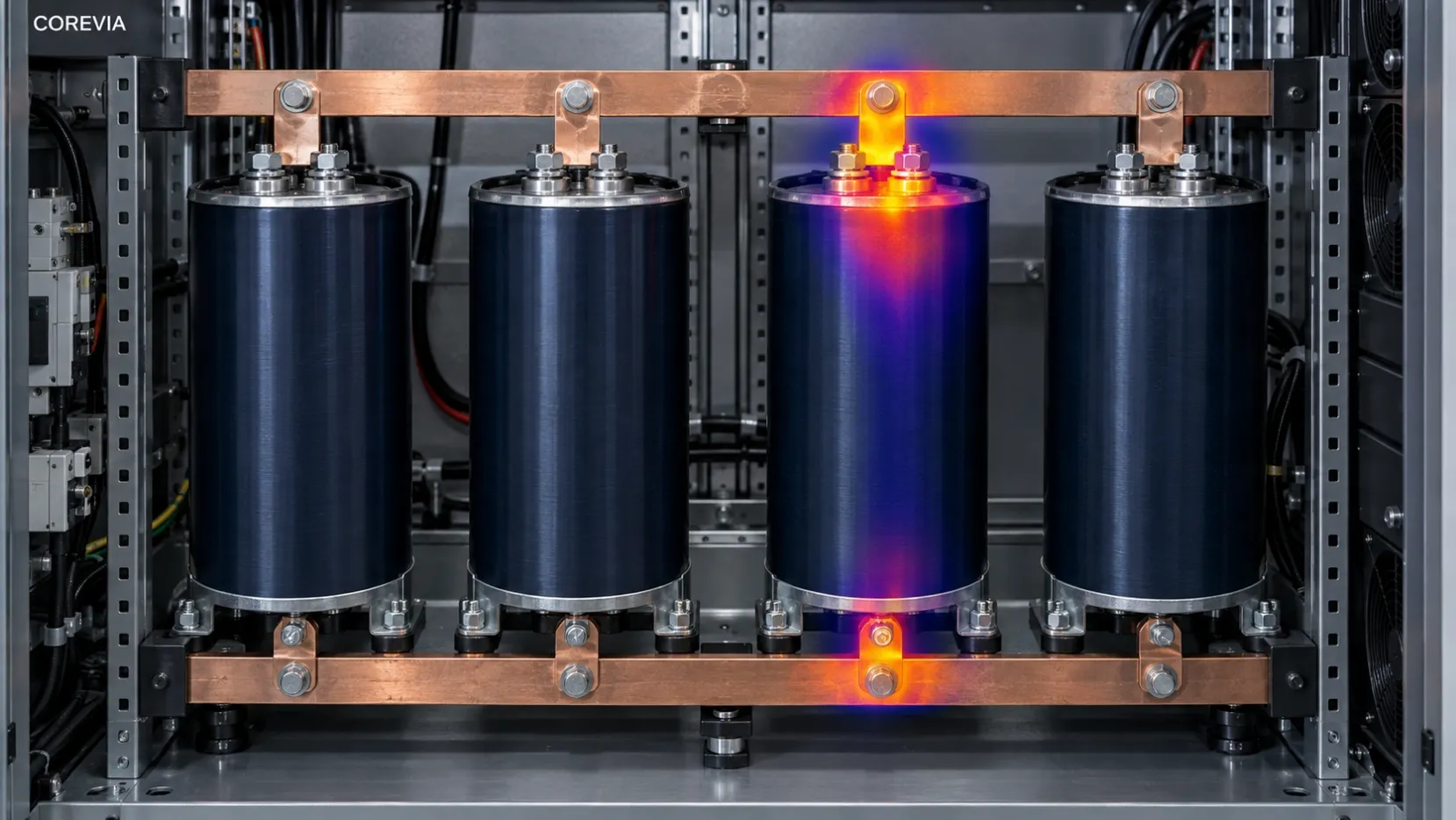
Several identical aluminum electrolytic capacitors are installed on the same DC bus. They have the same voltage rating, capacitance, case size and production series.
But during operation, one capacitor is noticeably hotter than the others.
It is easy to conclude that the hot capacitor is defective. Sometimes it is. However, when capacitors are connected in parallel, the installation around the capacitor can be just as important as the capacitor itself.
If the current paths are not reasonably balanced, identical capacitors may not experience identical electrical stress.
Identical Part Numbers Do Not Guarantee Equal Current
Parallel capacitors are commonly used in UPS systems, inverters, frequency converters, industrial drives and energy-storage converters.
The purpose is usually to increase total capacitance and share the AC current generated by the power-conversion circuit.
In an ideal arrangement, the load is distributed between the capacitors. In real equipment, every capacitor also has its own connection path through terminals, copper bars, fasteners and contact surfaces. Those paths are rarely perfectly identical.
A difference that looks small mechanically can affect how the current is divided, particularly when switching-frequency components are present.
How the Busbar Layout Affects Current Sharing
Consider a row of capacitors connected to one long copper bar.
If the positive and negative connections from the power circuit are both located near the same end of the bank, the capacitor closest to that end may have a shorter electrical path than the capacitor at the opposite end.
Other layout details can also affect the result:
Different branch lengths
Changes in busbar width or thickness
Asymmetrical positive and negative current paths
Additional joints on one branch
Unequal terminal contact resistance
Loose or incorrectly tightened connections
Oxidation or contamination between contact surfaces
The capacitor with the most favorable current path may carry more AC current than expected. At the same time, a poor connection can create additional heating directly at the terminal.
Both conditions may produce a hot capacitor, but they require different corrective actions.
The Location of the Heat Matters
A thermal image is useful, but it should be interpreted carefully.
If the entire capacitor body is warmer than the neighboring units, the capacitor may be carrying more current, may have higher internal losses, or may already be more aged.
If the highest temperature is concentrated around one terminal or busbar joint, contact resistance becomes a stronger possibility.
A loose terminal, uneven contact surface or damaged fastener can generate heat outside the capacitor. That heat can then enter the capacitor through the terminal assembly.
The visible hotspot is therefore only the starting point of the investigation.
Does the Problem Follow the Capacitor or the Position?
One of the most useful diagnostic questions is: does the abnormal temperature follow the capacitor, or does it remain at the same mounting position?
If a replacement capacitor becomes hot in exactly the same position, the busbar arrangement, terminal connection and local airflow should be investigated before another capacitor is blamed.
If the abnormal temperature follows the original capacitor during a controlled engineering comparison, the capacitor’s electrical condition becomes more suspect.
Any position comparison must be performed only during approved maintenance, after the equipment has been isolated and every capacitor has been safely discharged.
A Practical Inspection Sequence
Begin by recording the temperature of every capacitor under the same operating conditions.
The load, ambient temperature and operating time should be consistent. A temperature comparison taken during different load conditions can be misleading.
Next, record the physical position of each capacitor. Do not identify the units only by part number, because the mounting position may be the most important clue.
Then inspect:
Positive and negative busbar geometry
Current entry and return positions
Branch length and conductor cross-section
Terminal tightening torque
Contact-surface condition
Signs of discoloration, pitting or melted material
Local airflow and nearby heat sources
Capacitance and ESR of every unit
Operating history and previous replacements
Where suitable measurement equipment and safe procedures are available, compare the AC current in each capacitor branch.
The total current of the bank does not reveal whether every capacitor is carrying an equal share.
Do Not Ignore Capacitor Aging
Busbar layout is not the only possible cause.
One capacitor may have higher internal losses because of aging, electrolyte loss, internal connection damage or previous overheating. Once a capacitor begins running hotter, its electrical condition may deteriorate faster, increasing the temperature difference further.
This means the investigation should cover both the condition of the capacitor and the electrical and mechanical path connected to it.
Design Improvements
Better current sharing usually begins with a more symmetrical connection structure.
Practical improvements may include:
Using similar connection lengths for every capacitor
Keeping branch cross-sections consistent
Avoiding both power connections at one end of a long capacitor bank
Reviewing central-feed or diagonal-feed arrangements
Using flat, clean contact surfaces
Applying the specified terminal torque consistently
Keeping temperature sensors on critical bank positions
Verifying the design under real operating load
The correct arrangement depends on the equipment structure and current spectrum. It should be confirmed through measurement rather than appearance alone.
Final Takeaway
When only one capacitor in a parallel bank runs hot, replacing that capacitor may solve the immediate symptom. It does not necessarily solve the cause.
Check whether the temperature difference is associated with the capacitor itself, its terminal connection or its position in the busbar system.
If the same mounting position repeatedly becomes hot, the current path is sending a useful warning.
COREVIA
Aluminum Electrolytic Capacitor Solutions
Website: www.coreviacap.com
Email: sales@coreviacap.com