Can an Inverter DC-Link Capacitor Keep Running After a Cooling Fan Fails?
Fan failure changes the thermal conditions around an inverter DC-link capacitor. Check local temperature and ripple load before allowing continued operation.
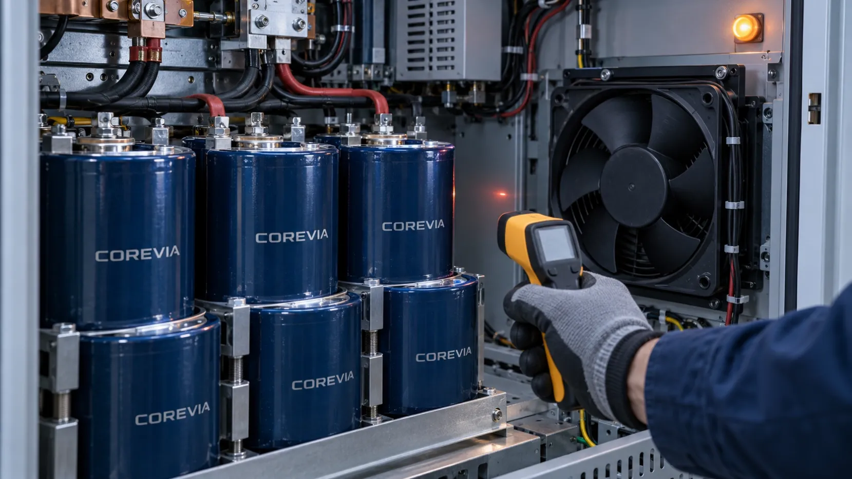
Do not assume an inverter DC-link capacitor can keep running at the same load after its cooling fan fails. Loss of airflow can raise the temperature around the capacitor and reduce heat removal while ripple current continues to generate internal heat. Continued operation is acceptable only if the equipment's fan-failure operating mode has been assessed against the exact capacitor series limits and the complete inverter safety design. Otherwise, the equipment needs an appropriate derating or shutdown response.
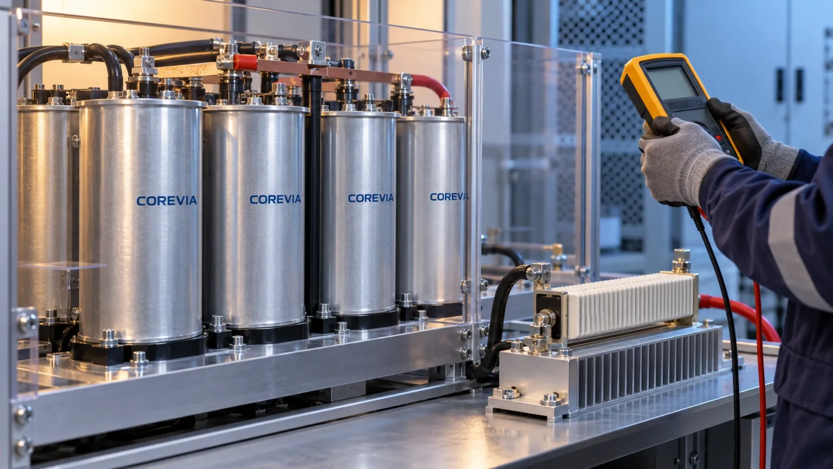
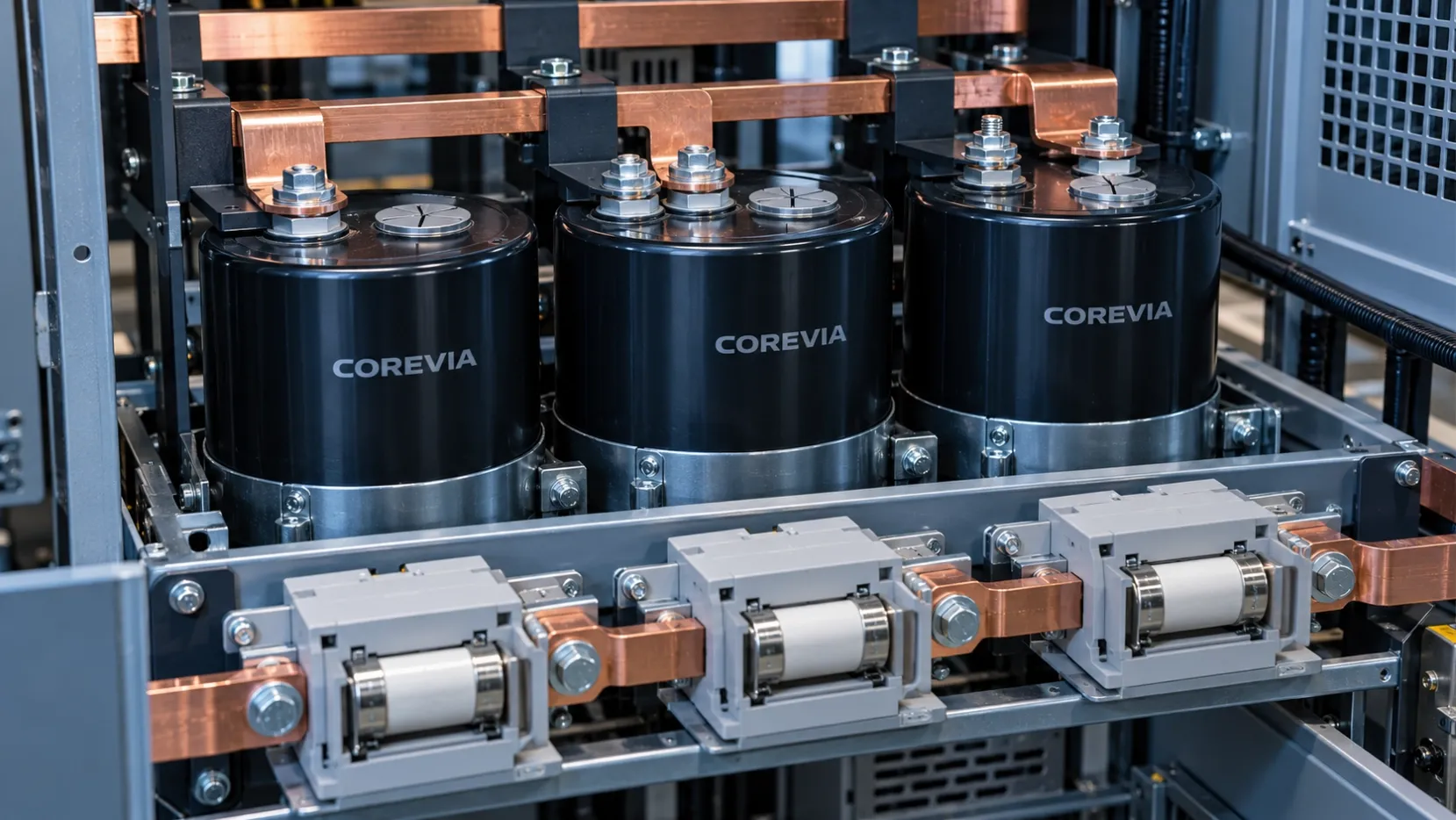
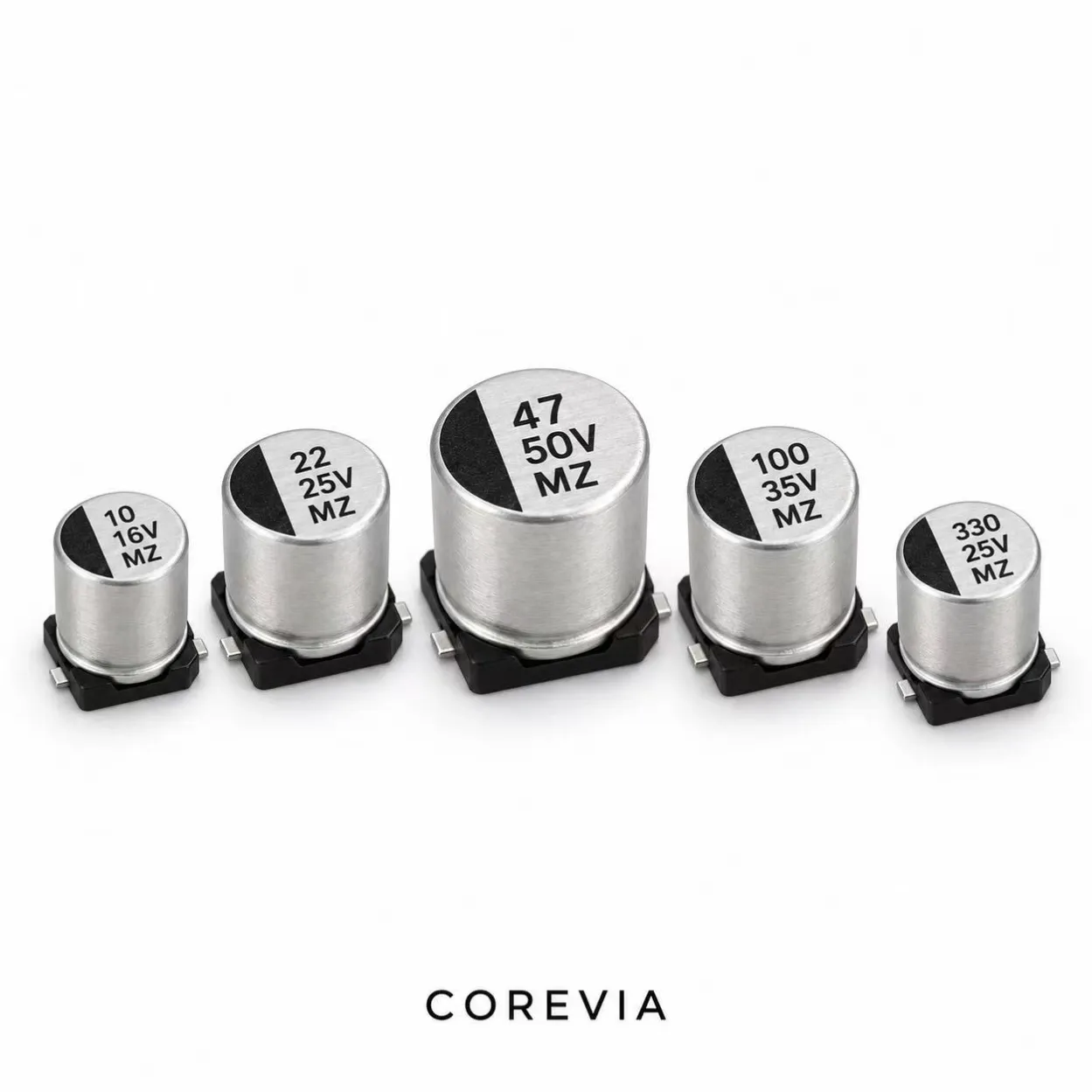
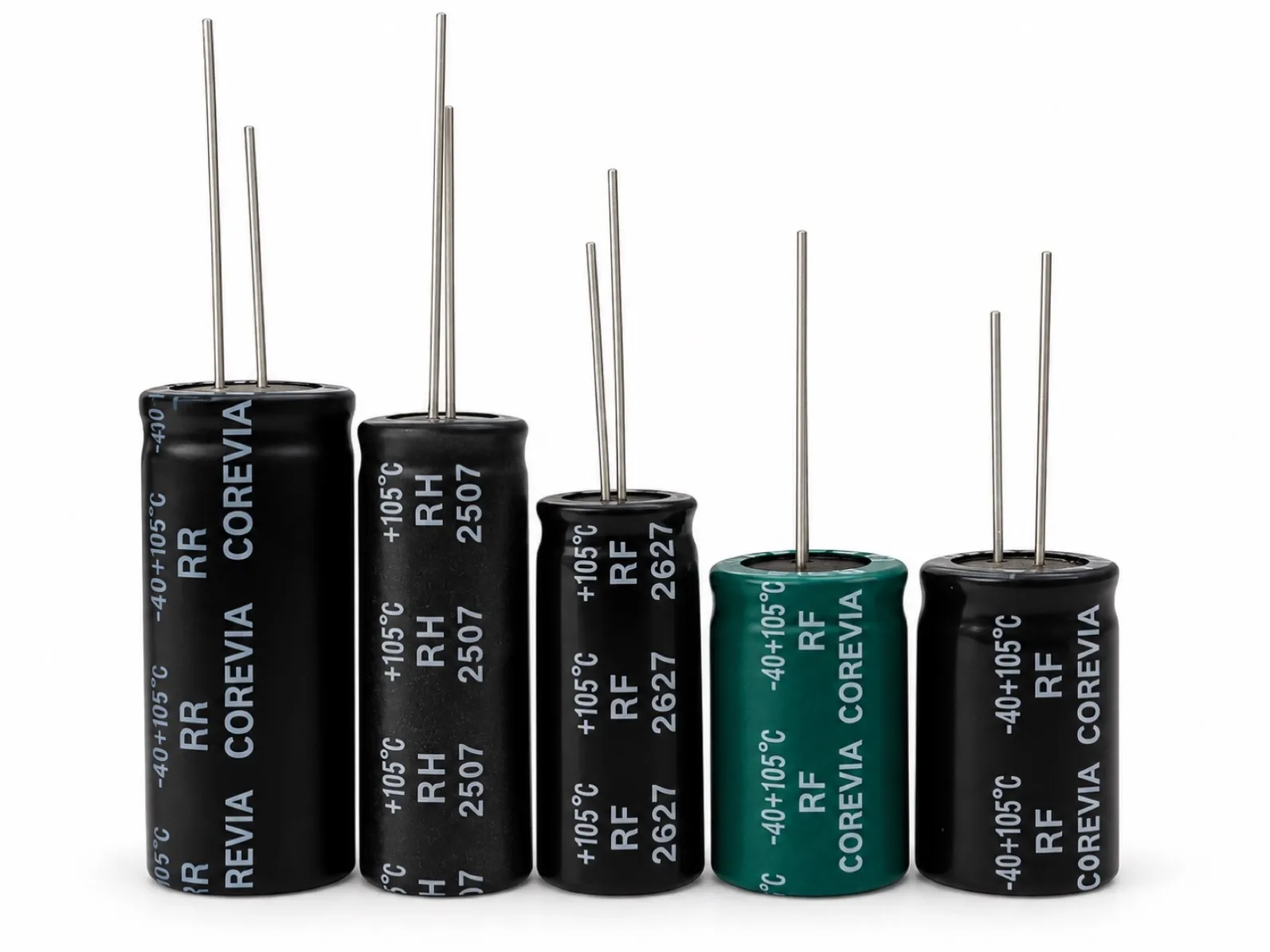
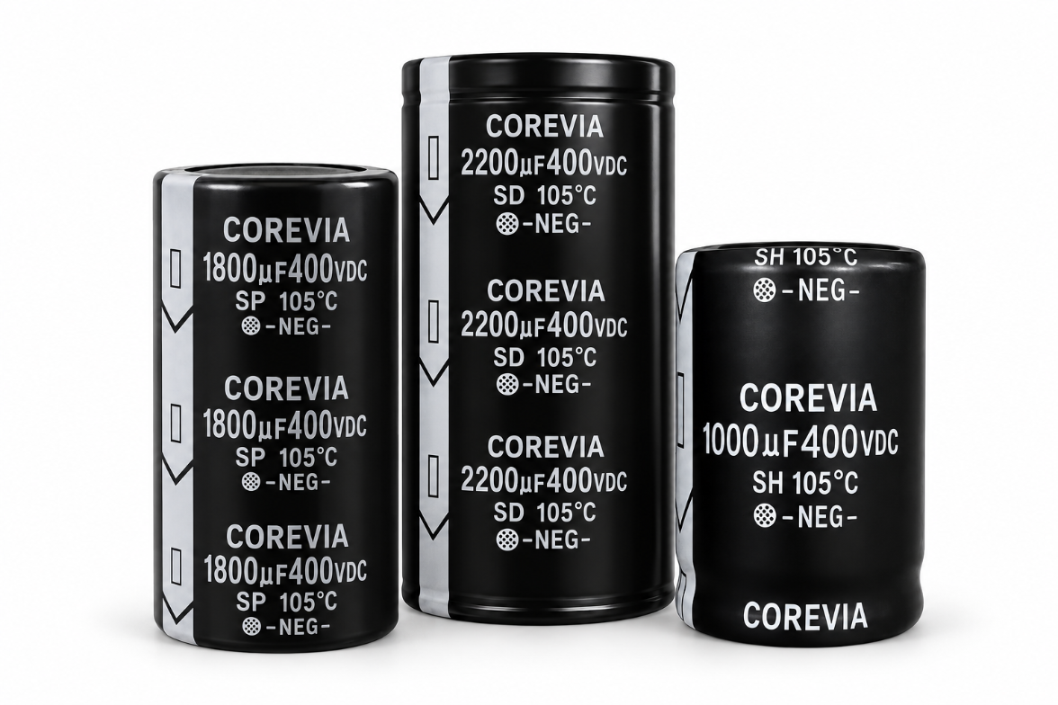
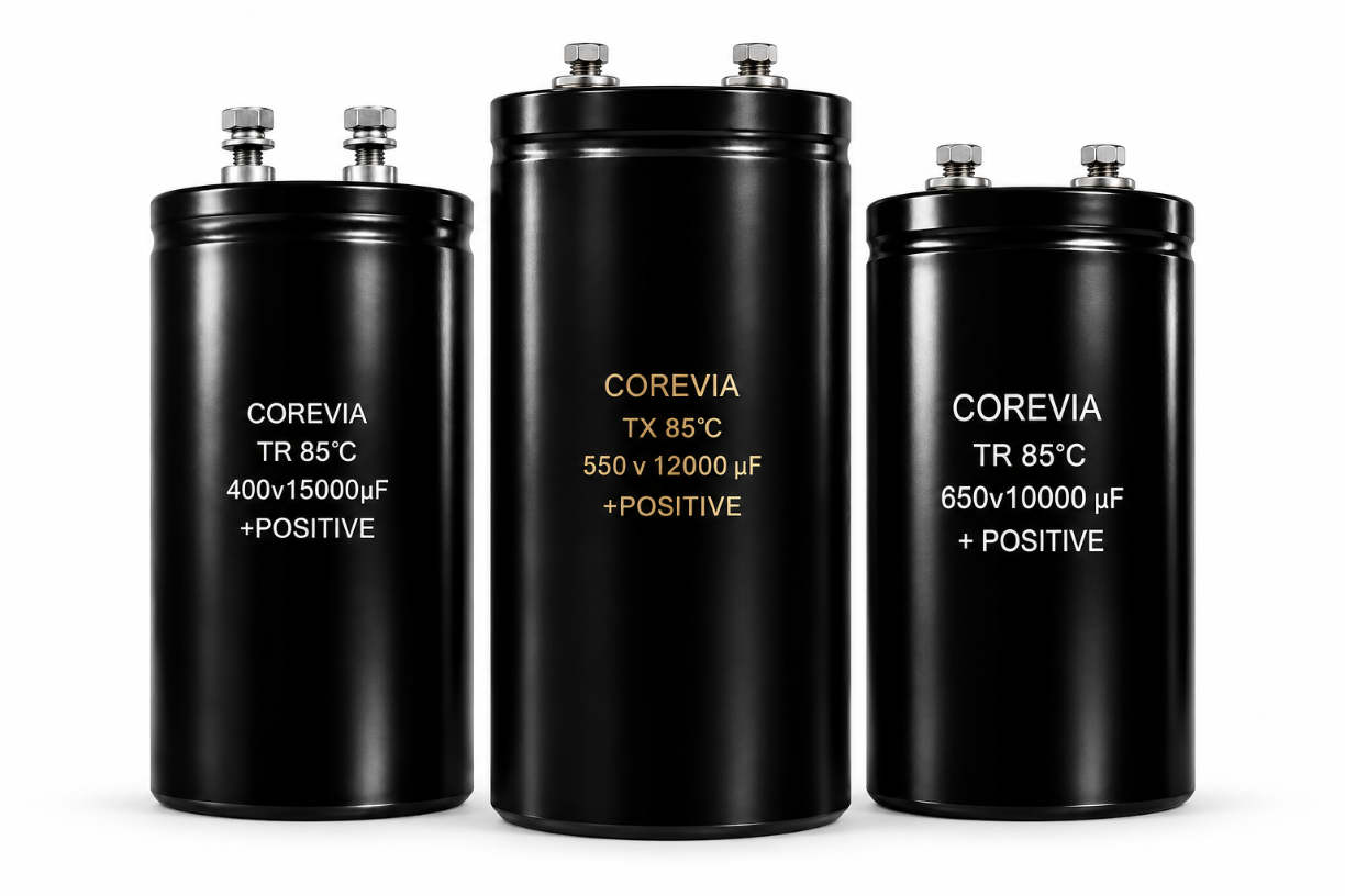
This is a practical question for cabinets that use forced air to cool a DC-link bank. COREVIA's screw-terminal aluminum electrolytic capacitors and snap-in aluminum electrolytic capacitors are different mounting families; the right choice depends on the exact part, its data sheet, electrical load and installed thermal conditions. A product-family page cannot establish a universal safe fan-off runtime.
What changes when forced airflow stops?
The capacitor still sees bus voltage and ripple current unless the inverter changes operating state. Its internal losses therefore may continue, but the surrounding air and nearby components can become warmer. The hottest capacitor position in a bank may differ from the location of the cabinet's general temperature sensor. A fan alarm alone reports a cooling fault; it does not measure the capacitor's actual thermal exposure.
Do not infer a fixed temperature increase or remaining life from a fan's nameplate airflow. Cabinet geometry, filters, heat sources, load profile and where the capacitor sits all affect the result. The equipment's own validated thermal measurements are the useful evidence.
What should be checked before allowing a fan-off mode?
Document the state that the inverter will enter when the fan fault is detected. Compare it with normal operation using the same measurement locations and a representative electrical load. The table separates observations from decisions; it does not prescribe a COREVIA temperature or current limit.
| Check | Evidence to collect | Decision it supports |
|---|---|---|
| Fault detection | Fan status signal, alarm timing and failed-fan test | Confirms the control system identifies loss of cooling |
| Electrical load | DC voltage, ripple-current waveform and duty cycle in the fault mode | Shows whether capacitor electrical stress changes |
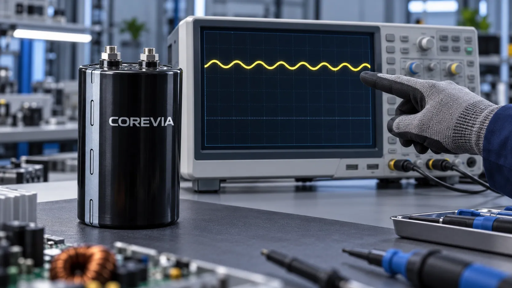
| Local thermal exposure | Air temperature near the most exposed capacitor and case-temperature trend | Shows how the installed bank heats without airflow |
| Exact capacitor limits | Selected part number, series data sheet and allowed operating conditions | Tests whether the fault mode remains inside part limits |
| Protective response | Load reduction, controlled stop and reset behavior | Defines what happens when limits cannot be met |
| Verification | Recorded fan-off test or validated thermal model | Supports release of the final equipment behavior |
Temperature should be checked under the actual cabinet configuration, including covers, filters and adjacent heat sources. A surface reading is useful for trend and comparison, but it is not automatically the capacitor's core temperature. A qualified engineer should interpret the selected series' thermal and ripple-current rules before approving continued duty.
What should the OEM send COREVIA for part selection?
Share the exact capacitor part numbers or candidate series, bank layout, maximum DC bus voltage, ripple-current spectrum, normal and fan-off load profiles, local ambient and measured case temperatures, and the proposed derating or shutdown sequence. Include the location of temperature sensors relative to the bank. This lets the capacitor selection be reviewed for the inverter application using evidence from the actual installation.
If the fan-off mode is still only a concept, label the temperatures as estimates. A different capacitor may be considered if the verified thermal and electrical conditions exceed the chosen series limits, but changing the capacitor alone does not replace a system-level fault response.
FAQ
Does a higher temperature rating mean the inverter can ignore a fan failure?
No. The rating is one part of the exact series specification. Ripple current, local temperature, mounting and the desired service life still need to be checked in the failed-fan condition.
Is one cabinet temperature sensor enough to protect every capacitor?
Not by assumption. The hottest bank position may be elsewhere. Validate sensor placement against measurements at representative capacitor positions.
Can the equipment run briefly at reduced load while a failed fan is replaced?
Only if that reduced-load mode has been verified against the exact capacitor limits and the equipment's safety requirements. Do not set a universal time allowance from a generic capacitor rating.
Designing an inverter fault response? Contact COREVIA with the bank details, normal and fan-off measurements, and candidate capacitor series for a capacitor-focused application review.