Oct 9, 2026Application Guides
LED Driver Capacitors: How to Choose for LED Lighting
Choose LED driver capacitors by voltage, capacitance, local temperature, ripple current and lifetime class — then validate the finished driver inside its real enclosure.
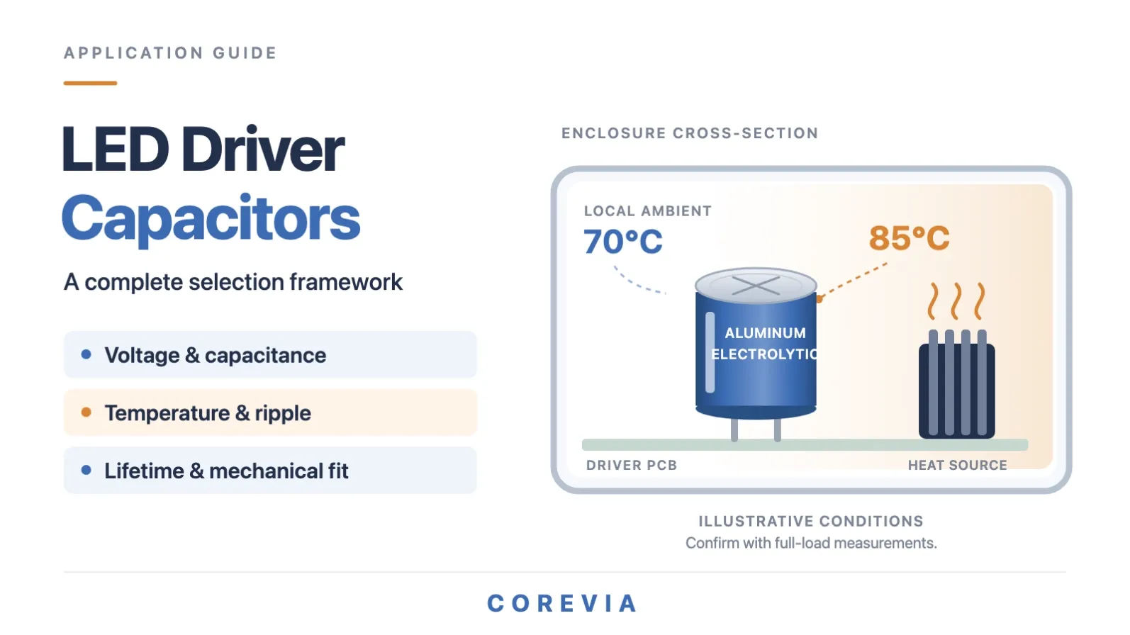
An LED driver is one of the harshest environments an aluminum electrolytic capacitor will ever work in: a sealed case, almost no airflow, and power components radiating heat centimeters away. Yet the capacitors inside are expected to outlast the fixture they power. Here is a complete framework for choosing LED driver capacitors — circuit position, capacitance and voltage, local temperature, ripple current, lifetime, and final validation.
Quick answer: Choose LED driver capacitors by checking capacitance and voltage headroom, local operating temperature, ripple current at the relevant frequency, and required service life. Use the exact series datasheet to confirm ratings and correction factors; then verify fit and performance at full load inside the finished enclosure.
Start with the circuit position
A LED driver is not one capacitor job — it is two or three, each with different demands. Identify the position first, because it decides which parameters dominate:
- Input and DC-bus capacitors store energy after the rectifier and PFC stage. Their capacitance sets the bus ripple and the hold-up time through line dips; their voltage rating must cover normal bus voltage plus the tolerance and transients the design allows.
- Output filter capacitors carry the load's pulsating current at the switching frequency. Here the ripple current rating and ESR dominate — and capacitance is constrained by the control loop and startup behavior, not "the bigger the better."
Circuit position | Main role | Key selection parameters | Verify on the finished driver |
Input / DC bus | Energy storage, hold-up | Capacitance, voltage headroom, ripple at line frequency | Bus ripple at low line, dip ride-through |
Output filter | Smoothing pulsed load current | Ripple current rating, ESR, capacitance within loop limits | Output ripple, startup, dimming behavior |
Set capacitance and voltage headroom
Choose capacitance for the required performance. Translate the circuit's energy-storage, ripple and startup requirements into a capacitance target, then check it against tolerance: aluminum electrolytics are commonly specified at ±20%, and the capacitance also drifts over life — designs must work at end-of-life values, not just nominal. The control loop often caps how much output capacitance the driver can tolerate, so more is not automatically safer.
Check voltage across operating conditions. Compare the capacitor's rated voltage against the maximum continuous voltage in the position — including bus overvoltage at high line and any transient the design intentionally allows. There is no universal derating percentage that fits every driver; what matters is that the worst-case continuous stress in your design stays below the rating with margin, in writing, on the datasheet's terms.
Measure local temperature, then select the temperature class
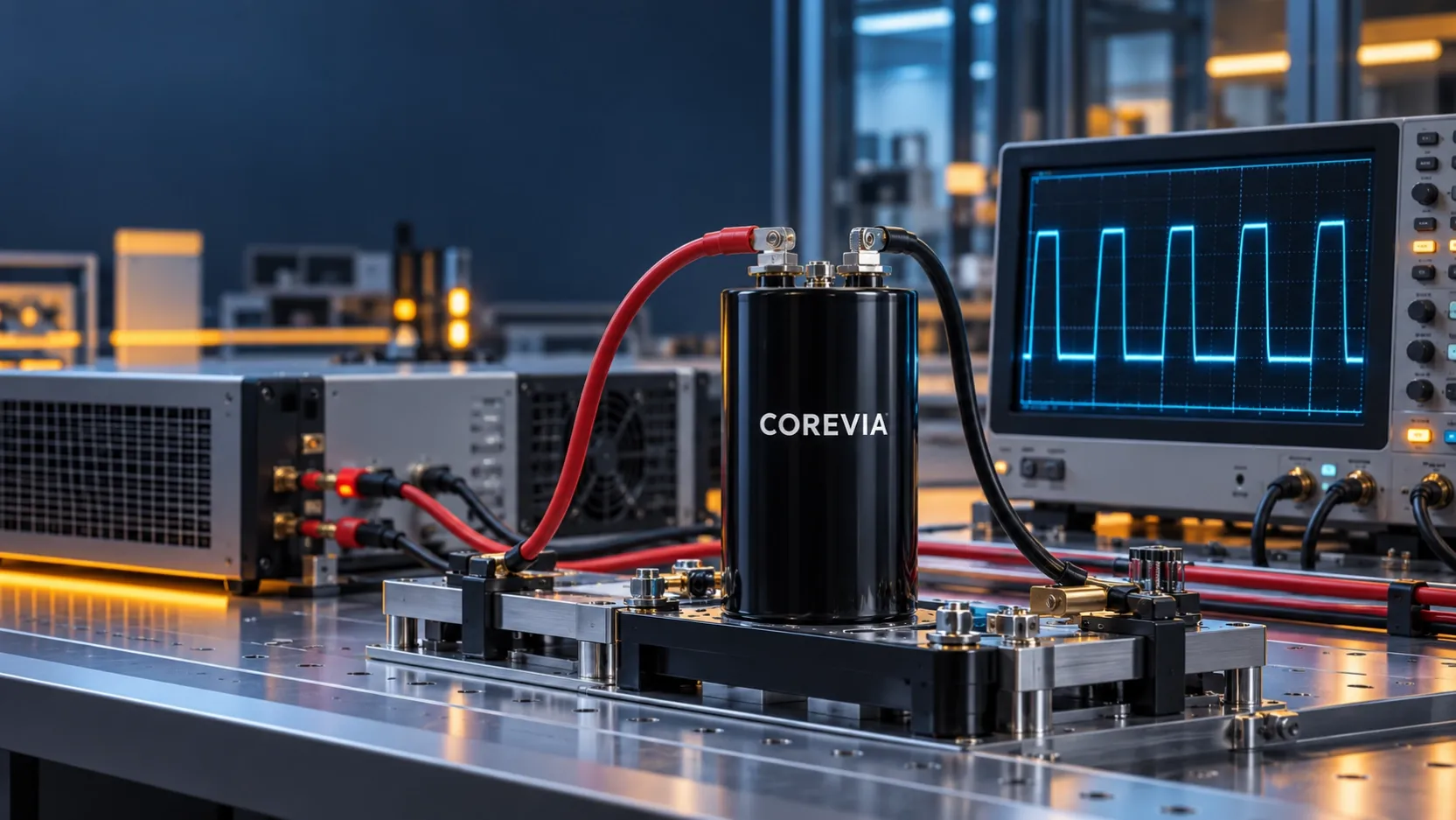
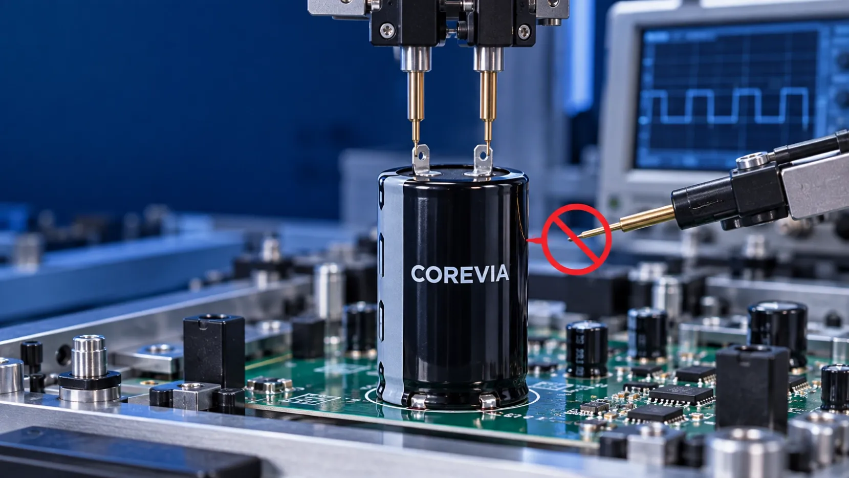
Local ambient is different from room temperature. The specification sheet of the driver may say 50°C ambient — but inside a sealed enclosure, centimeters from a hot inductor and MOSFETs, the air around the capacitors is hotter than the room and hotter than the case exterior suggests. Measure with a thermocouple near the capacitor body, at full load, in the hottest allowed operating condition.
What a 105°C rating does — and does not — tell you. The rating is the maximum ambient at which the series delivers rated performance for its endurance hours. It is a boundary, not a lifetime promise: a 105°C capacitor is not guaranteed years at 105°C. The rating buys headroom; the actual service life comes from the local temperature and ripple, as covered in our guide to 85°C vs. 105°C aluminum electrolytic capacitors.
What you measure | What it represents |
Room / spec-sheet ambient | The number on the driver's datasheet — rarely what the capacitors feel |
Local ambient near the capacitor | The air temperature the capacitor actually lives in — the number to select against |
Case surface temperature | Midpoint reference; the core always runs hotter |
Internal hot spot | Not directly measurable; estimated per the manufacturer's model |
Check ripple current, ESR and frequency corrections
Compare ripple current on the same basis. Datasheet ripple ratings are quoted as RMS current at a stated frequency and temperature, with series-specific correction factors for other conditions. Convert your circuit's actual ripple spectrum to RMS, apply the correction at your switching frequency, and compare like for like — a multiplier table from one series cannot be applied to another.
Understand ESR and self-heating. At a given frequency, the power dissipated inside the capacitor is approximately the square of the RMS ripple current times the ESR — which is why two capacitors with identical capacitance can run dramatically different temperatures in the same socket. ESR falls with temperature and varies strongly with frequency, which is exactly why the comparison must happen at your operating point. The reliability mechanics behind this are in our guide to how ripple current and ESR affect capacitor reliability.
Estimate lifetime from the rated conditions
Use the 10°C rule as a qualified estimate. For most aluminum electrolytic series, service life roughly doubles for every 10°C the internal temperature sits below the rated temperature — a qualified approximation, valid inside the conditions and limits the manufacturer states. The full method, including ripple corrections, is in our guide to capacitor lifetime, temperature and ripple current.
Translate the mission profile into a lifetime target. A driver advertised for 50,000 hours does not need a 50,000-hour capacitor — it needs a capacitor whose estimated life at the real local temperature and ripple exceeds the driver's duty profile. A driver running 12 hours a day in a 70°C enclosure asks a very different question than one running continuously at 85°C. Rated life at rated conditions is the starting point of that calculation, never the answer to it.
Confirm mechanical fit and validate the finished driver
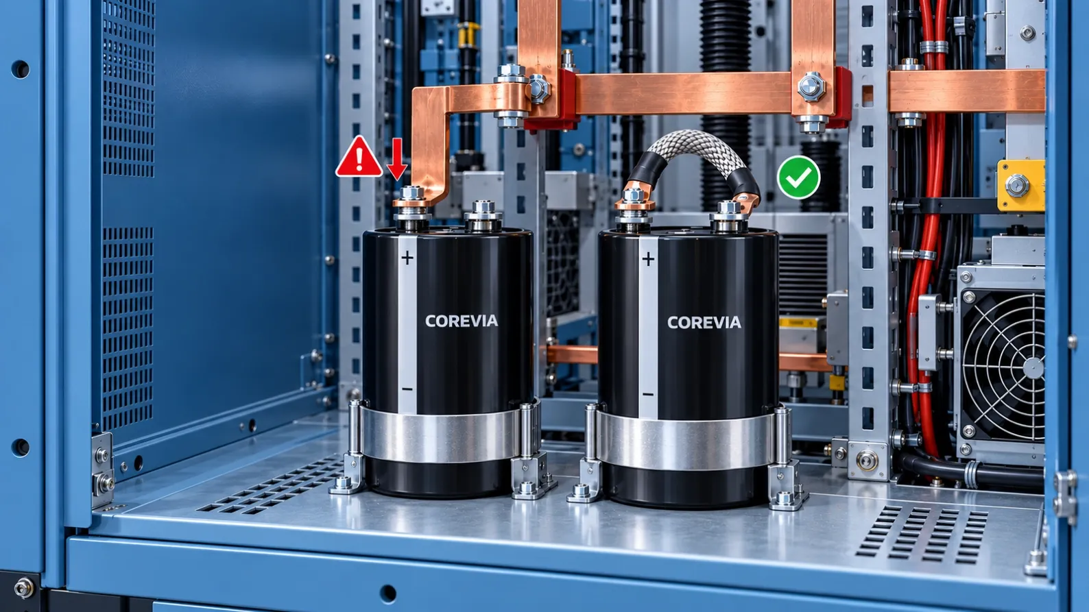
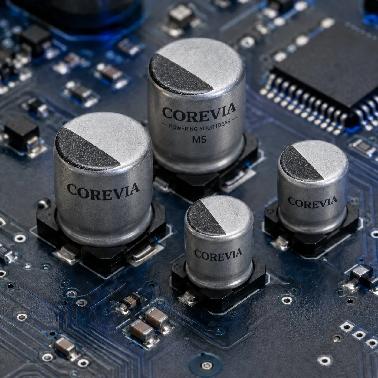
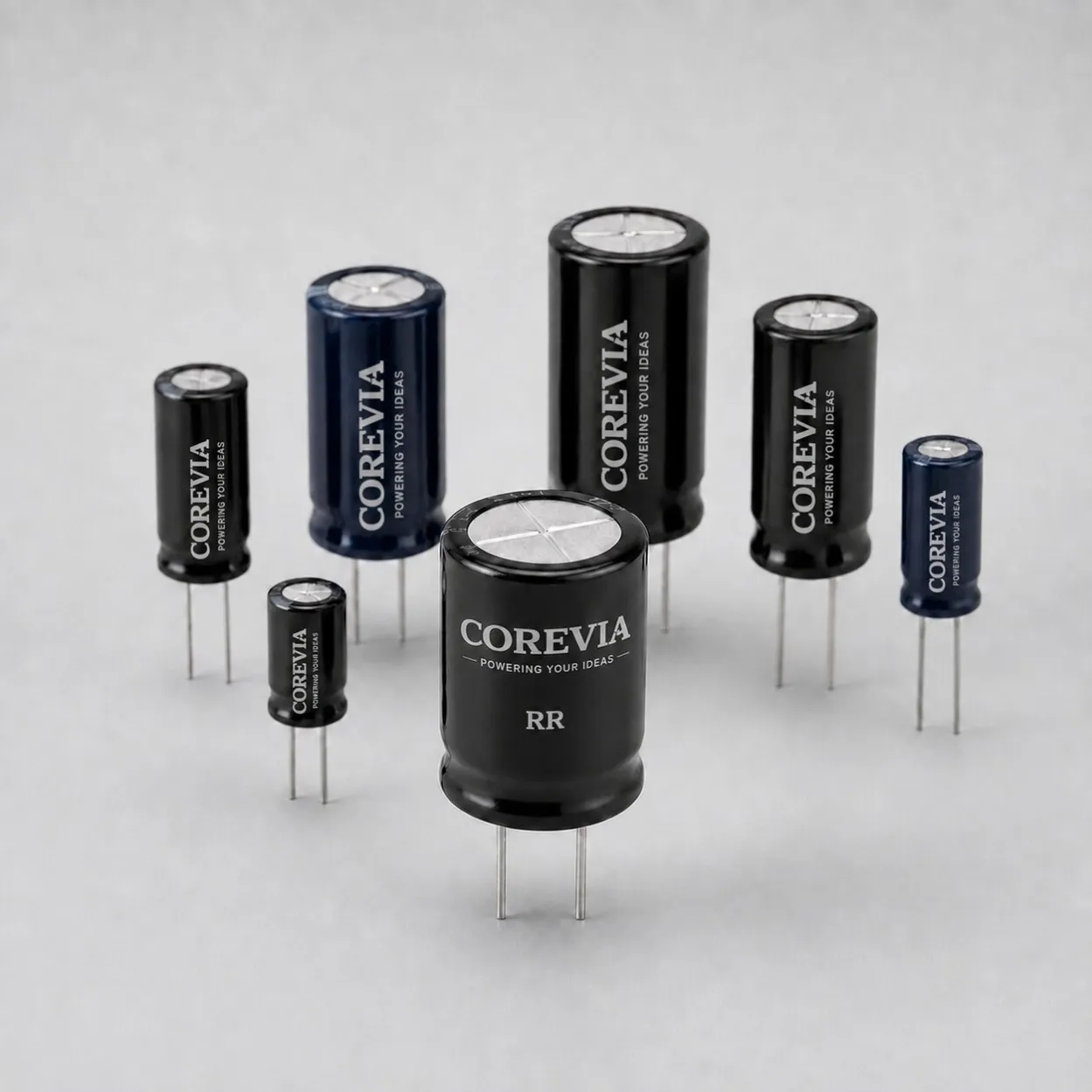
Match the package to the PCB and enclosure. Radial-leaded capacitors cover most LED driver boards — our radial-leaded aluminum electrolytic capacitors page lists the current lineups. Check diameter and lead spacing against the PCB footprint, case height against the enclosure, polarity marking against assembly, and vent clearance: a vent that cannot open safely inside a sealed case is a design failure waiting for a trigger.
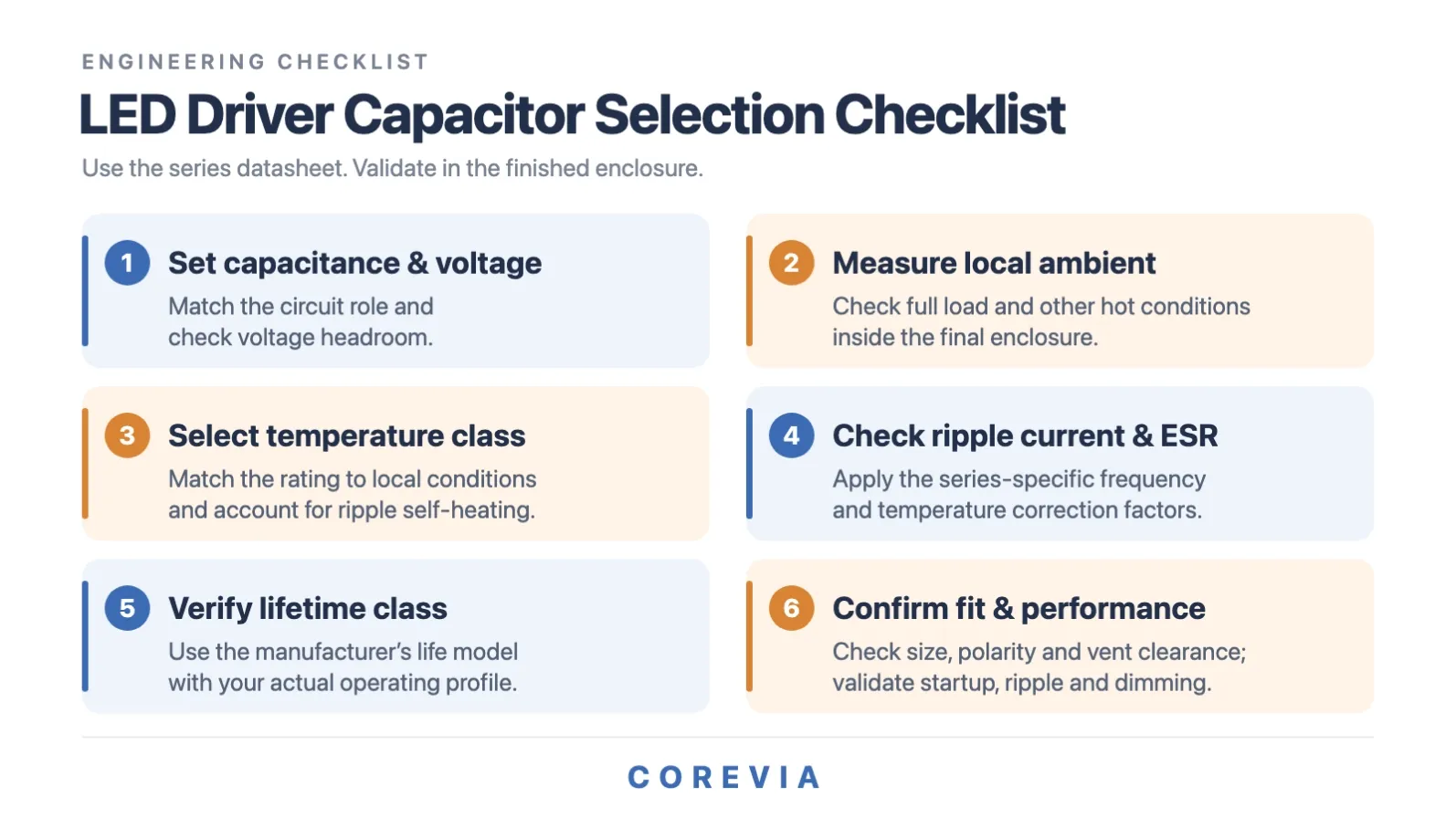
Run the final selection checklist. The six steps below compress this entire framework into a pass/fail list. Run it across the full input voltage range, the full load range, and every dimming mode the driver supports — capacitors that behave at full load can still misbehave at low-load dimming, where convection and ripple patterns change.
Frequently asked questions
What capacitors are used in LED drivers?
Aluminum electrolytic capacitors are the standard choice where bulk energy storage and filtering call for substantial capacitance — the input stage, DC bus and output filter of the driver. Film and ceramic capacitors take other roles in the circuit depending on topology.
How do I choose the capacitor value for an LED driver?
Derive capacitance from the circuit's energy-storage, ripple, startup and control-loop requirements, then check tolerance and end-of-life drift. Validate the chosen value in the finished driver, not just in the spreadsheet.
Do LED drivers need 105°C capacitors?
For hot or enclosed drivers, a 105°C series is usually the right direction — but the temperature rating alone does not establish suitability. Local temperature, ripple-induced heating, rated lifetime class and required service life all have to check out together.
How long do LED driver capacitors last?
It depends on the series endurance class, the local temperature, the ripple current and the operating profile. Manufacturer life models — commonly built around a doubling of life for each 10°C below rated temperature — turn those inputs into an estimate.
Can a failing capacitor cause LED lights to flicker?
It can: lost capacitance or risen ESR may push output ripple beyond what the driver's control handles smoothly. But flicker also comes from dimmer mismatch, control behavior or supply conditions — so diagnose before replacing anything.
Find capacitors for your LED driver
Send us the circuit position, capacitance, voltage, local temperature, ripple conditions, target lifetime and size limits, and COREVIA will identify candidate series and provide datasheets for evaluation: [email protected] · WhatsApp +86 137 7126 2062.