Screw-Terminal Capacitor Busbar Stress: Installation Guide
Learn how rigid busbars, heavy cables and poor alignment can stress screw-terminal aluminum electrolytic capacitors and cause unreliable connections.
The Connection Looks Tight—So Why Does It Keep Failing?
A screw-terminal aluminum electrolytic capacitor can test normally and still develop an unreliable connection after installation. The terminal bolt may be tight, yet one connection repeatedly runs hot, loosens after service or reacts to equipment vibration.
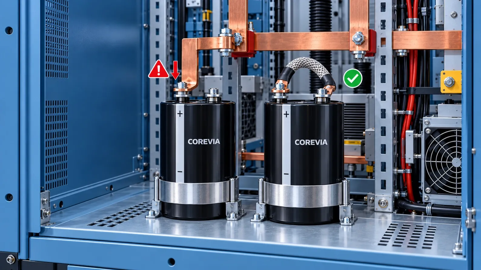
Before blaming the capacitor, inspect the mechanical load around it. A rigid busbar, unsupported cable or misaligned mounting hole may continuously push or pull on the terminal.
The Terminal Should Carry Current, Not Structural Load
The capacitor body should be supported by the correct mounting clamp. Its terminals are electrical connection points; they should not carry the weight of the busbar, cable or neighboring components.
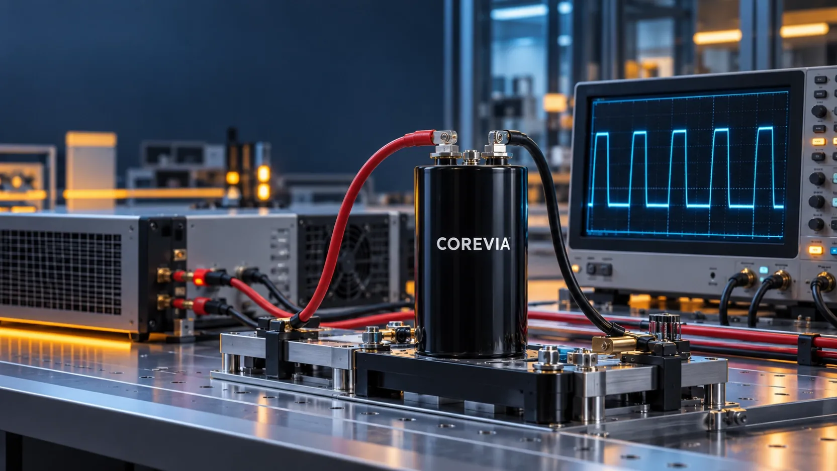
If a rigid busbar must be forced into position before the bolt can be installed, the connection already contains mechanical stress. Tightening the bolt hides the misalignment but does not remove it.
Common Sources of Mechanical Stress
- Busbar holes do not naturally align with the capacitor terminals.
- A heavy cable hangs directly from the terminal.
- The capacitor clamp is loose or fitted at the wrong height.
- Vibration causes a long rigid connection to move repeatedly.
- A replacement capacitor has a slightly different terminal position or case height.
- Thermal expansion has no flexible section to absorb movement.
A Simple Alignment Check
After the equipment is switched off, isolated and fully discharged, loosen the connection using the approved maintenance procedure. Observe the busbar or cable lug before moving it by hand.
If it immediately springs sideways, drops downward or pulls away from the terminal, the connection was storing mechanical force. The busbar should naturally meet the terminal without being used as a lever.
Why More Tightening Force Is Not the Answer
Extra torque cannot correct poor alignment. It may damage the terminal hardware or create a new reliability problem. Always use the tightening torque, screw type, washers and mounting method specified for the exact capacitor series.
Do not copy one torque value across different capacitor sizes or suppliers. Terminal dimensions and mounting hardware can differ.
When a Flexible Connector Helps
A short flexible copper braid or another approved flexible connection can help isolate the capacitor terminal from vibration, assembly tolerance and thermal movement. It does not replace correct busbar design, but it can prevent the terminal from becoming the mechanical weak point.
The cable or busbar must still be independently supported, and the capacitor body must remain firmly secured by its clamp.
Practical Inspection Checklist
- Confirm that the capacitor clamp supports the body securely.
- Check whether the busbar naturally aligns with both terminals.
- Support heavy cables independently.
- Inspect for discoloration, fretting marks or loose hardware.
- Verify the specified terminal and clamp torque.
- Check movement during vibration and temperature changes.
- Recheck alignment whenever a capacitor is replaced.
What to Send for Technical Review
Provide the capacitor model, case dimensions, terminal drawing, busbar layout, mounting photos, tightening torque, vibration conditions and any thermal images of the connection.
That information helps separate a capacitor problem from a mechanical installation problem.
COREVIA Application Support
COREVIA supports aluminum electrolytic capacitor selection and application review for UPS systems, inverters, energy-storage converters, charging equipment and industrial drives.
A reliable DC-link design depends on the capacitor, electrical conditions and mechanical installation working together.