Does an Inverter DC-Link Capacitor Bank Need Precharge at Startup?
A DC-link capacitor bank may need a controlled precharge path to keep startup current within the inverter's component limits. Check the real circuit and startup waveform before approval.
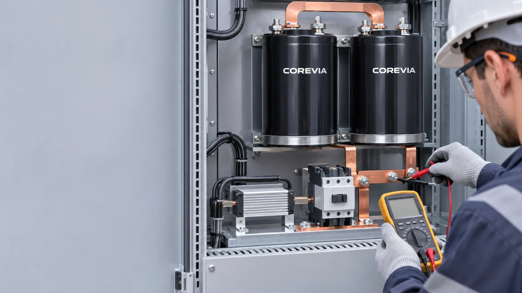
An inverter DC-link capacitor bank needs a controlled precharge process when direct connection to its supply would produce startup current beyond the limits of the rectifier, switchgear, wiring or capacitor connections. The answer is a system design decision, not a universal feature of the capacitor alone. Verify the actual bank capacitance, source voltage and impedance, current path, switching sequence and measured startup waveform before approving the circuit.
What does precharge protect during startup?
An uncharged DC-link bank initially presents a large voltage difference to its supply. The charging current depends on the source, wiring and intentional current-limiting elements. A high peak can stress contactors, rectifiers, fuses, busbars and capacitor terminals even when the steady-state ripple-current rating is acceptable. Precharge introduces a controlled path before the main connection is made, then transfers to normal operation under defined conditions.
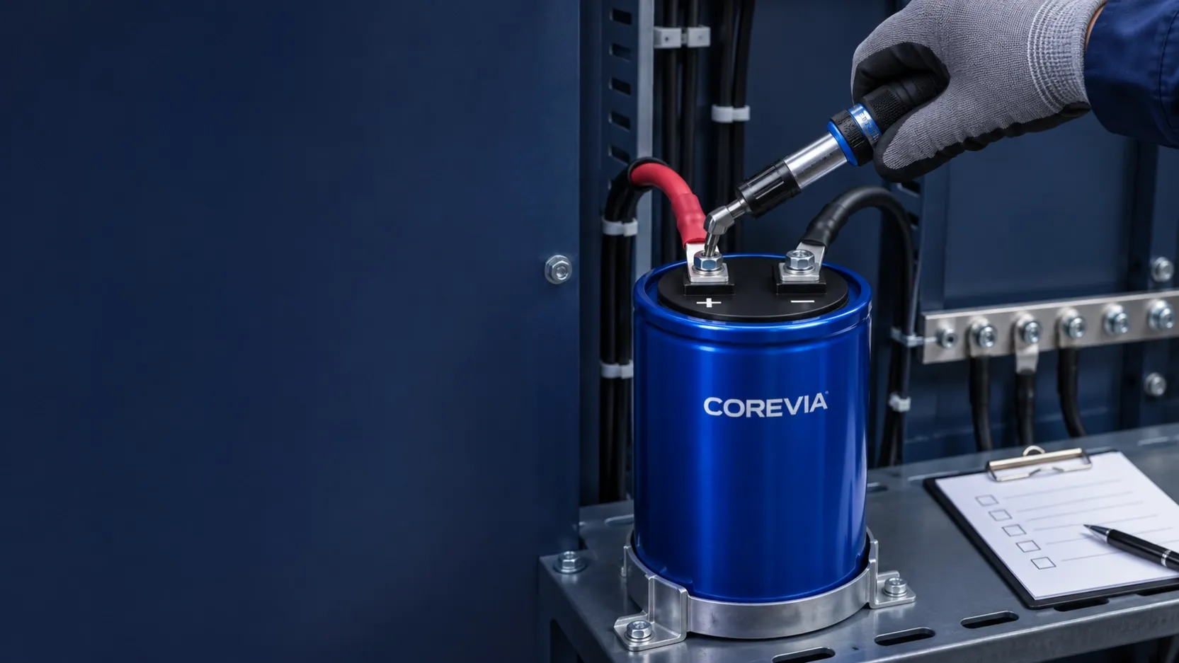
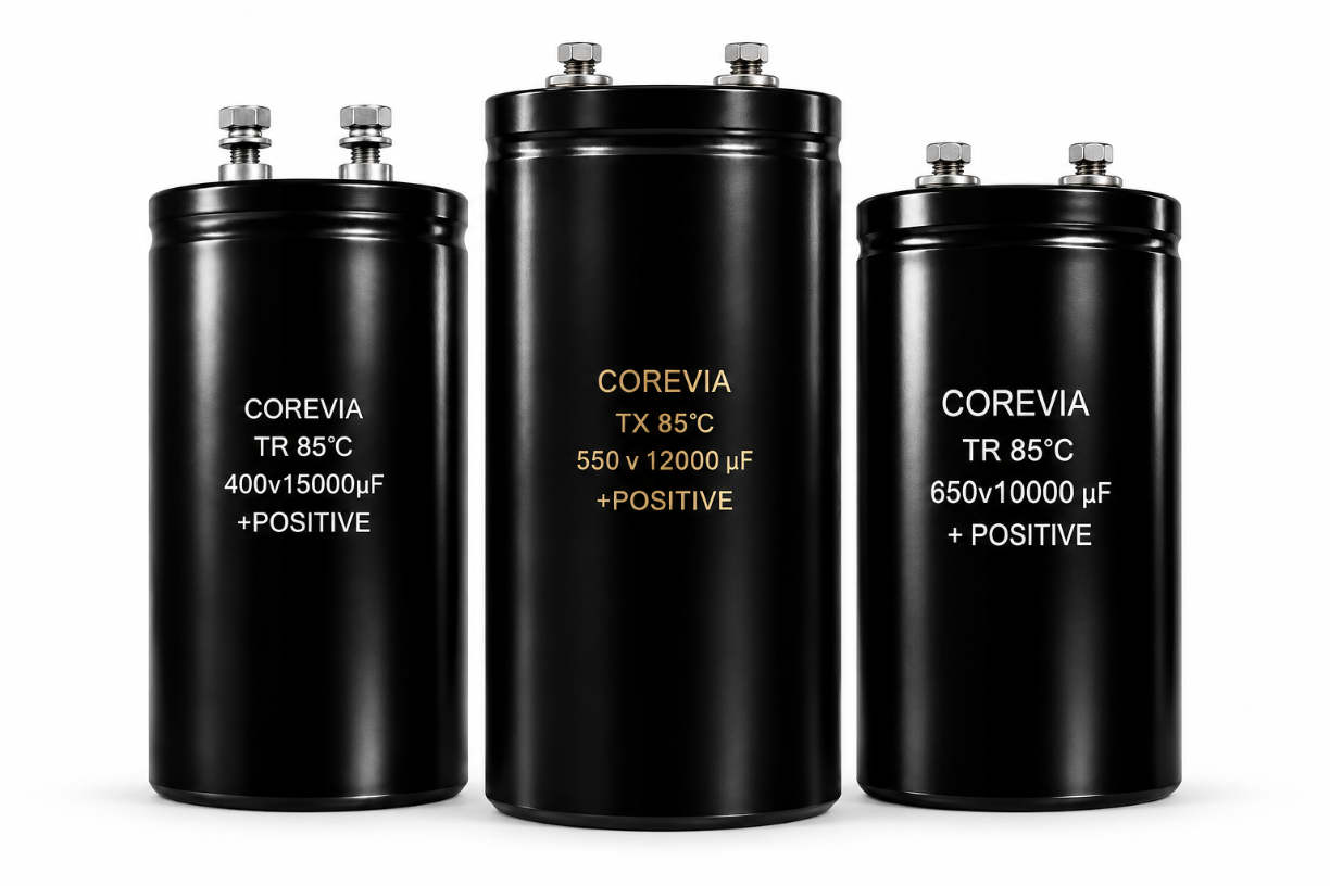
COREVIA's screw-terminal capacitor family serves industrial power applications, but a family page is not a startup-current approval for a particular bank. A design review needs the exact COREVIA series, part number, number of capacitors, wiring layout and operating duty.
| Design input | Why it matters | Evidence to request |
|---|---|---|
| Supply voltage and source impedance | Set the available charging drive | Circuit diagram and operating range |
| Total bank capacitance and connection layout | Affect stored energy and current paths | Exact parts, quantity and busbar drawing |
| Precharge component and bypass sequence | Determine current limit and transfer behavior | Control schematic and timing logic |
| Startup frequency and abnormal restarts | Add repeated thermal and switching duty | Duty profile and fault-restart logic |
| Measured bus voltage and current | Show what the real system does | Captured startup waveforms |
How should the precharge path be reviewed?
First define the worst credible startup condition: minimum or maximum supply voltage as applicable, a discharged bank, temperature range and restart behavior. Calculate a first-pass charging profile for the proposed current-limiting path, then check that the resistor or other limiting element, contactor, rectifier and wiring can withstand the pulse and repeated duty. Do not copy a resistor value or bypass delay from another inverter; the correct values depend on this circuit.
Set a clear transfer condition, such as an approved DC-bus voltage threshold, and verify it on the hardware. If the main contactor closes before the bank is sufficiently charged, a large remaining voltage difference can recreate the current surge. If the precharge path stays active too long, its thermal rating can be exceeded. Fault handling should cover a failed precharge component, a stuck contactor, loss of supply and an immediate restart after shutdown.
The discharge path is a separate design issue. A bank can retain voltage after power-off even if startup precharge works correctly; see whether a DC-link capacitor bank needs a discharge resistor. For equipment that trips after a capacitor replacement, use the separate precharge troubleshooting guide. Neither function replaces a verified safe-work procedure.
What should be measured before production approval?
Record DC-bus voltage and charging current from the first connection through bypass. Repeat the test across the approved supply range and relevant temperature and restart conditions. Check the waveform for peak current, charge duration, switching transients and any unexpected reverse voltage. Compare component stresses with their own ratings and the exact capacitor-series requirements. Inspect the capacitor bank and connections after testing for abnormal heating, loose joints or visible damage.
When asking COREVIA to review a capacitor choice, send the bank schematic, capacitor part numbers and quantity, peak bus voltage, startup waveform, repeat rate, ambient temperature and mechanical layout. COREVIA can assess the capacitor application against its series data; the inverter designer remains responsible for protection and control of the complete circuit.
FAQ
Is the capacitor ripple-current rating enough to approve startup current?
No. The published ripple-current condition concerns operating current under stated test conditions. Startup charging is a different transient; review its peak, duration, frequency and current path separately.
Is precharge always required for a single capacitor?
No universal component-count rule applies. The need depends on the supply impedance, capacitance, switching components and allowed startup stress. Evaluate the actual circuit even if it contains only one capacitor.
Can the precharge resistor also discharge the bank after shutdown?
Only if the system circuit intentionally provides and validates that discharge path. Do not assume a startup resistor remains connected after the bypass contactor operates or after power is removed.
For a part-specific capacitor review, send the circuit and startup measurements through COREVIA's contact page.