Does a DC-Link Capacitor Bank Need a Discharge Resistor?
A DC-link bank can stay charged after power-off. Learn when a discharge path is needed, what to specify, and why maintenance must verify bus voltage.
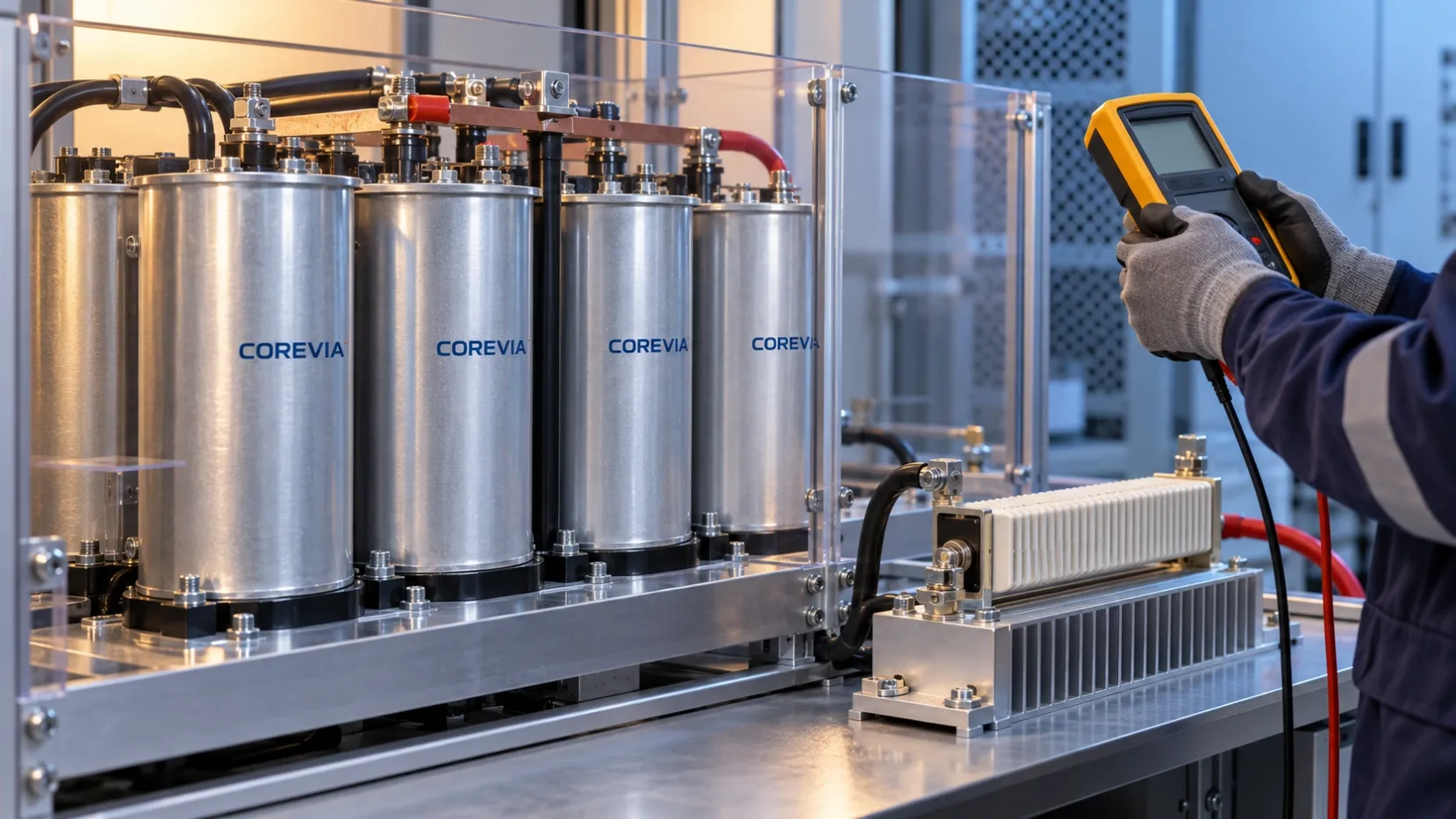
A DC-link capacitor bank needs a defined way to discharge whenever the equipment safety design requires the bus to reach a specified voltage after power is removed. A permanent bleeder resistor is one option; a controlled discharge circuit is another. Neither the capacitor's normal leakage nor an unverified load should be treated as a dependable discharge path. The equipment designer must set the required end voltage and time, design the path for the worst-case bus and stored energy, and require a voltage check before service.
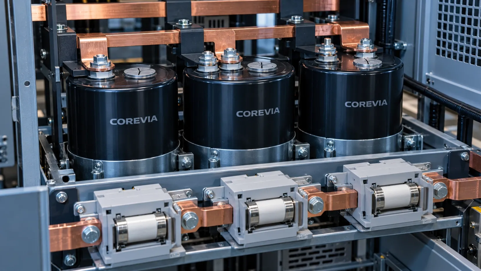
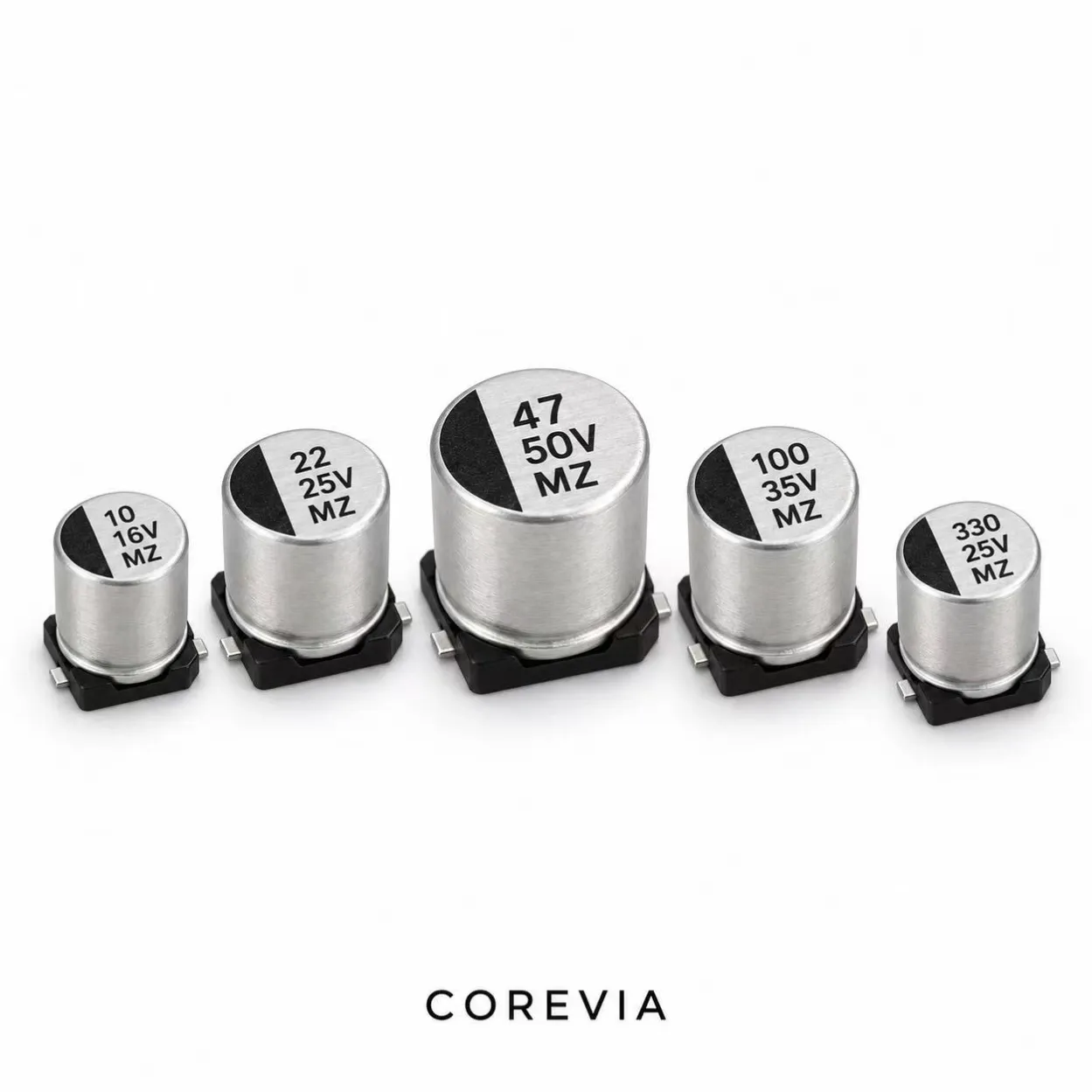
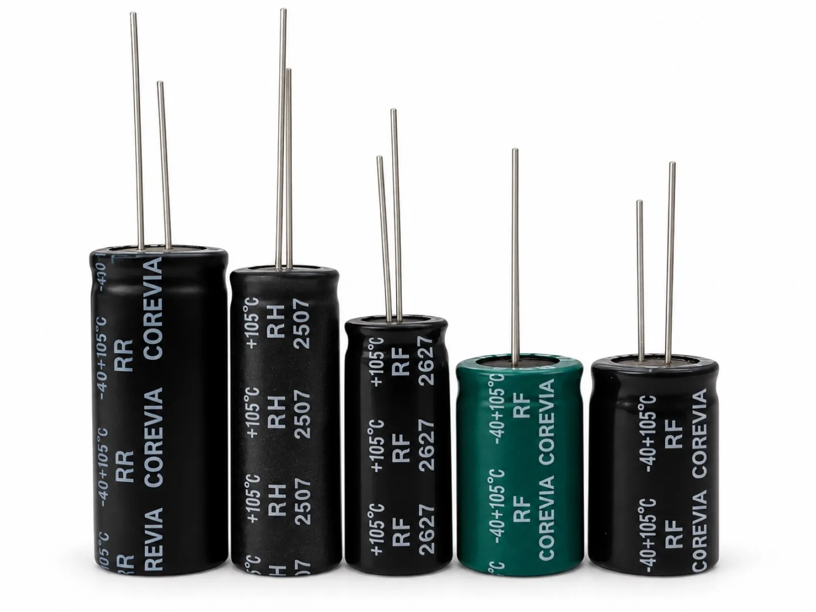
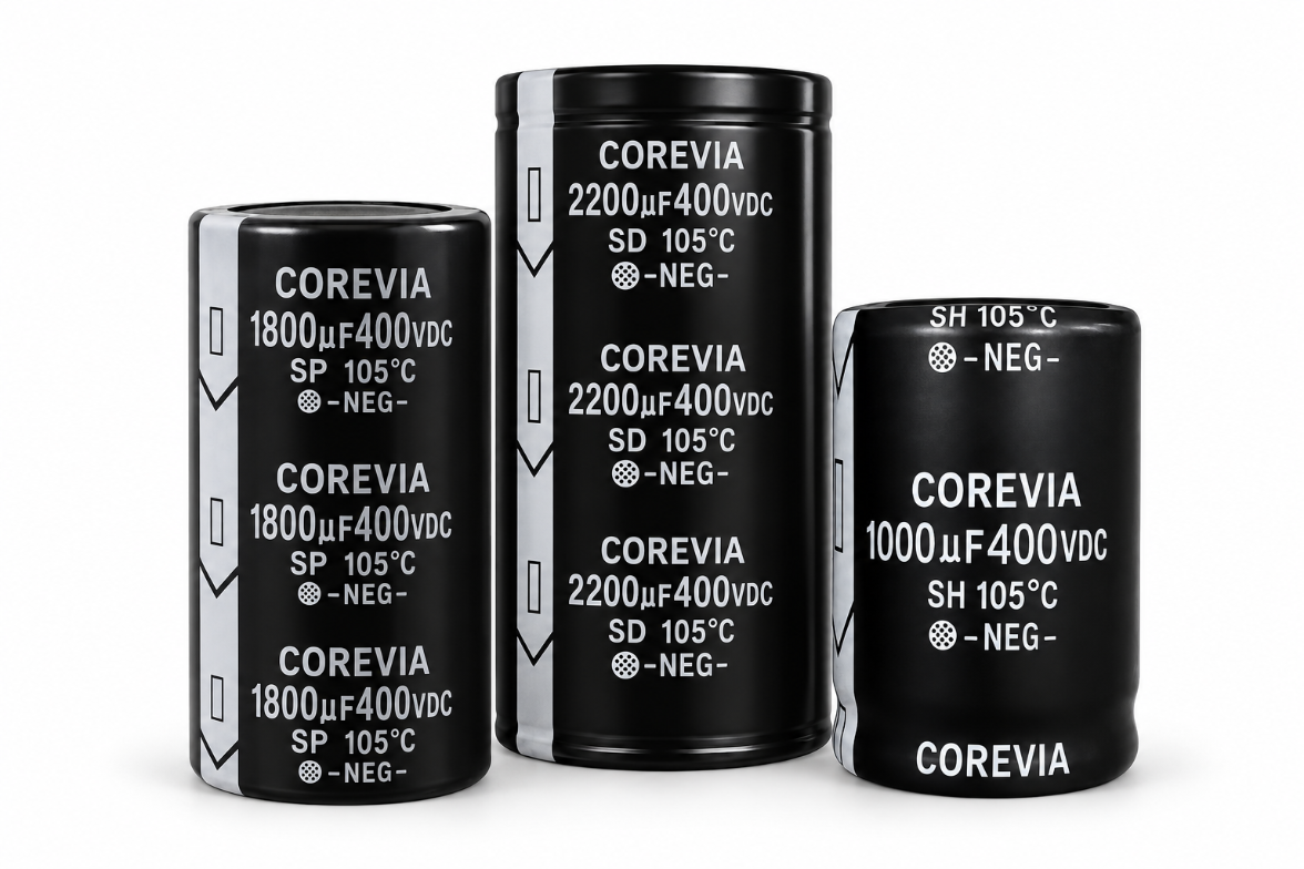
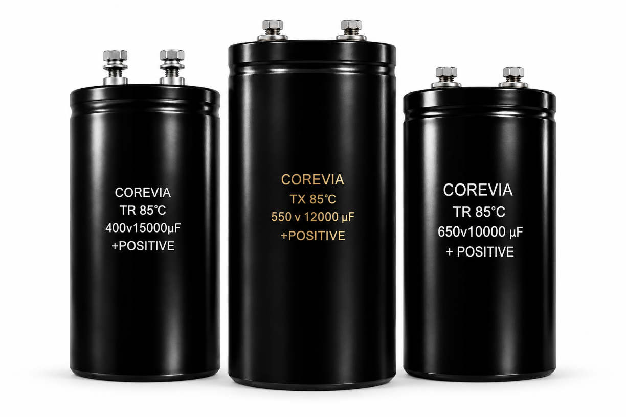
This is a system-level decision for inverter, UPS and power-conversion equipment. COREVIA supplies screw-terminal aluminum electrolytic capacitors and snap-in aluminum electrolytic capacitors for designs that may use a DC link. The exact capacitor data sheet helps establish the bank's capacitance, voltage and operating limits; it does not replace the equipment's discharge and access requirements.
Why can the bus remain charged after shutdown?
Opening an input switch separates the source from the bank but does not remove the energy already stored in its capacitors. The discharge behavior depends on what remains electrically connected after shutdown. A downstream load may disconnect, an active circuit may need power or a control signal, and capacitor leakage is neither a specified service-discharge method nor a fixed value over life and temperature.
Treat a visible power-off indicator as a control-state signal, not proof of zero bus voltage. A qualified service procedure should identify the bus measurement points and verify the voltage using a suitably rated instrument before anyone touches conductive parts.
Which discharge arrangement fits the equipment?
A bleeder resistor connected across the bank can provide a passive path while the circuit remains intact, but it also dissipates power during normal operation. A switched resistor can reduce steady-state loss, yet its switch and control behavior must be reviewed for loss of power and fault conditions. The choice follows the equipment's required discharge behavior, access rules and fault analysis; there is no universal resistor value for all COREVIA capacitors.
| Design question | Why it matters | Evidence to record |
|---|---|---|
| What is the maximum charged bus voltage? | Sets electrical stress and initial stored energy | Measured or specified worst-case bus condition |
| What is the bank's maximum effective capacitance? | More capacitance can extend discharge time and raise energy | Exact capacitor parts, quantities and applicable tolerance |
| What voltage must be reached, and by when? | Defines the system acceptance test | Equipment safety requirement and service procedure |
| Is the path always connected or switched? | Determines normal losses and failure modes | Circuit diagram and power-off sequence |
| Can the resistor handle the energy and heat? | Discharge and repeated cycles can overheat an undersized part | Resistor pulse, continuous-power and thermal review |
| How is safe access verified? | An indicator or timer alone may not prove discharge | Test points, instrument rating and verification procedure |
This table is a review checklist, not a component specification. For a simple isolated RC path, voltage falls approximately exponentially, so both the starting voltage and the total effective capacitance affect the time. Real equipment can have multiple banks, switching paths or external sources; validate the complete circuit rather than assuming a single ideal resistor calculation covers it.
What should the purchaser send for capacitor selection?
Identify the exact bank topology, candidate COREVIA part numbers, maximum bus voltage, ripple-current spectrum, operating temperature and required capacitance. Add the equipment's discharge target, circuit drawing and service-access concept so the capacitor selection can be checked in context. COREVIA can review the capacitor-related data for the proposed inverter application; the equipment designer owns the discharge circuit, protective devices and safety validation.
If the discharge arrangement changes the bank's number of units or normal operating conditions, repeat the capacitor selection check. A resistor chosen for a safety target does not by itself establish that voltage, ripple-current, life or mounting requirements are met.
FAQ
Will capacitor leakage discharge the bank quickly enough?
Do not rely on leakage as a specified discharge path. Its value depends on the part and conditions, and it does not establish a verified time to a safe service voltage.
Can a pre-charge resistor also discharge the bank?
Only if the actual switching circuit deliberately connects it across the charged bank after shutdown and the resistor is rated for that duty. A pre-charge resistor in a charging path is not automatically a discharge path.
Is waiting a fixed number of minutes enough before maintenance?
No fixed waiting period proves the actual bus voltage. Follow the equipment's approved isolation and discharge procedure, then measure at the specified points with a suitable instrument before access.
Designing an inverter or UPS DC link? Contact COREVIA with the bank drawing, operating conditions and candidate capacitor details for a capacitor selection review. Have your equipment safety engineer specify and validate the discharge path.