Can PCB Depanelization Stress Installed Aluminum Electrolytic Capacitors?
Board separation can load capacitor leads and solder joints. Review support, cut paths and post-process checks before approving an assembled PCB.
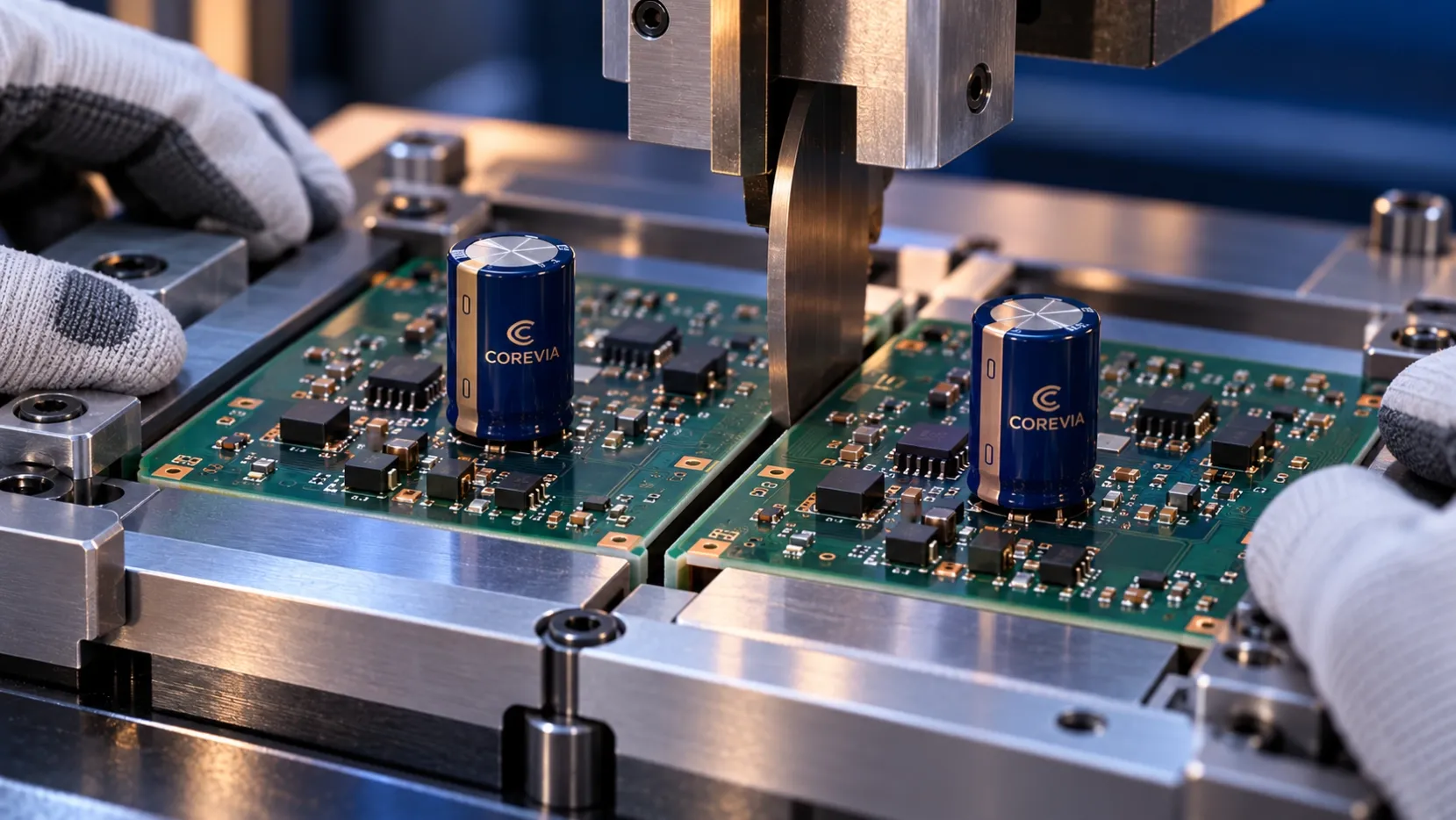
Yes. Separating an assembled PCB can bend the board or transmit impact through capacitor leads and solder joints. Support the panel near the cut, review the route and component placement, then qualify the actual separation process on finished assemblies. No single clearance or allowable board deflection applies to every COREVIA capacitor and PCB.
Where can depanelization load the capacitor?
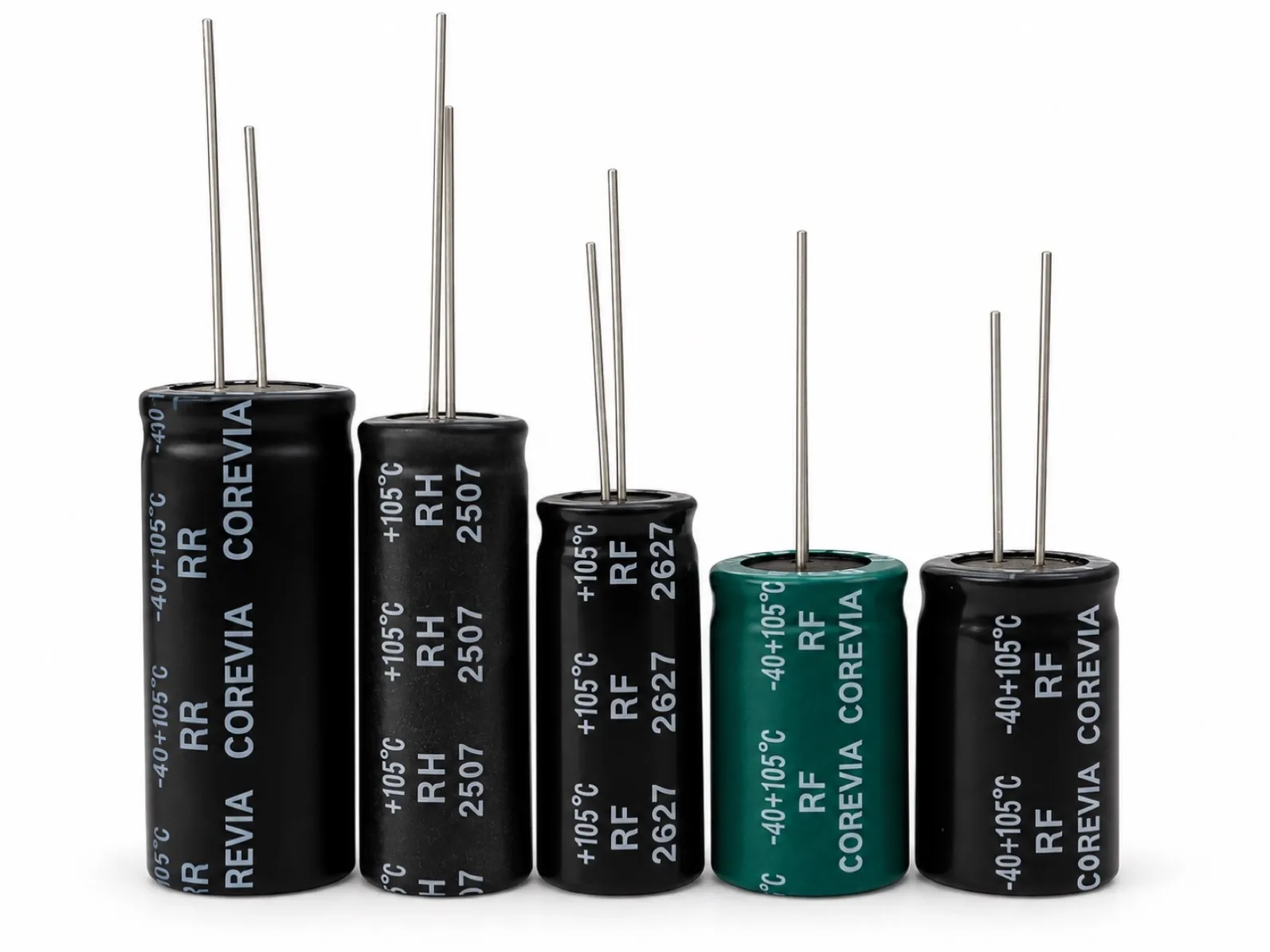
A radial aluminum electrolytic capacitor is attached to the board through its leads and solder joints. If the PCB flexes during manual breaking, routing or another separation method, the mounting points may move relative to the capacitor body. This can stress leads, joints and the seal area. The risk depends on the board layout, capacitor size, mounting height, tooling and separation method.
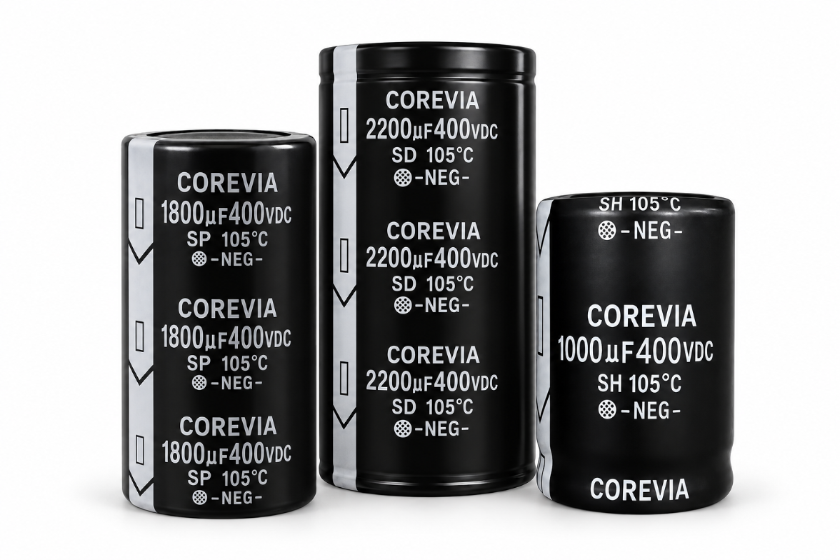
Electrical ratings alone do not establish mechanical suitability for a specific depaneling process. Start with the exact COREVIA radial capacitor drawing and mounting information. For larger PCB-mounted parts, review the relevant COREVIA snap-in capacitor construction and any required body support as a separate case.
What should the production team check before separation?
Map the cut path, component positions and support points on the actual panel. Keep the capacitor from being used as a handhold. Avoid forcing the assembly around a fixed capacitor body. If the process changes, repeat the qualification with the revised tool and board layout.
| Check | Evidence to collect | Decision to make |
|---|---|---|
| Cut path and placement | Panel drawing, component coordinates and cut method | Whether the capacitor or its joints sit in a high-flex area |
| Board support | Fixture contact points and a trial run | Whether the board remains supported while the cut completes |
| Handling | Operator work instruction and observed handling | Whether hands or tooling push on the capacitor body |
| Inspection | Before-and-after photographs and electrical checks | Whether the finished assembly meets its acceptance criteria |
If leads must be formed before soldering, review the separate lead-forming guide. Lead forming and board separation are different process steps and should be validated independently.
How do you qualify the finished assembly?
Run representative boards through the intended production setup. Compare the capacitor body, lead exits, solder joints and PCB around the mounting holes before and after separation. Check for visible movement, cracks or damage, and perform the electrical and functional checks specified for the assembled product. Record the tool, fixture, operator method and acceptance criteria so that later changes trigger a review.
For a new COREVIA part or an uncertain layout, send the capacitor part number, PCB thickness, mounting drawing, panel cut path, separation method and relevant photographs through the COREVIA contact page. We can review the capacitor information available for the exact part; the finished PCB process still needs validation in your assembly.
FAQ
Is manual snapping safe if the capacitor is away from the cut line?
Distance alone is not proof. The board can flex beyond the immediate cut area. Validate the actual panel, support and handling method.
Can a visual inspection replace electrical testing?
No. Visual inspection can find obvious physical damage, while electrical and functional checks address different failure modes. Use both as required by your assembly acceptance plan.
Does one approved depaneling fixture cover every capacitor size?
No. A change in capacitor size, mass, mounting position or board design can change the load path. Reassess the revised assembly and process.