Can You Force a Snap-In Capacitor Into a PCB With the Wrong Hole Pitch?
A snap-in capacitor should not be forced into a PCB footprint that does not match its terminal pattern. Check the exact series drawing, hole pattern and polarity before assembly.
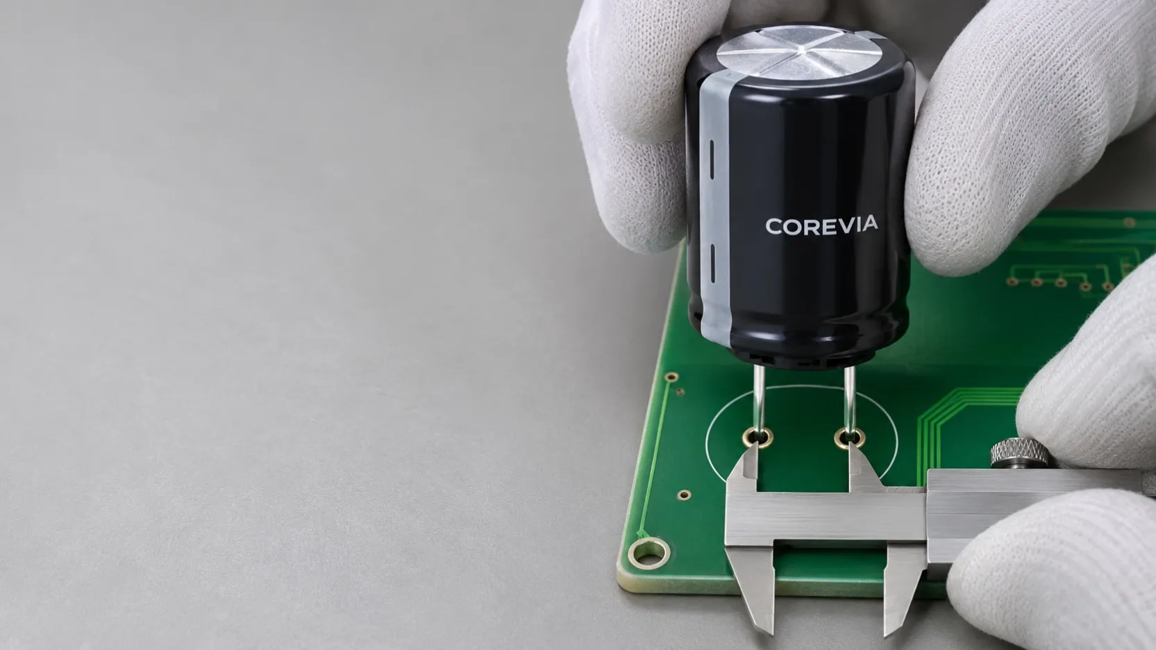
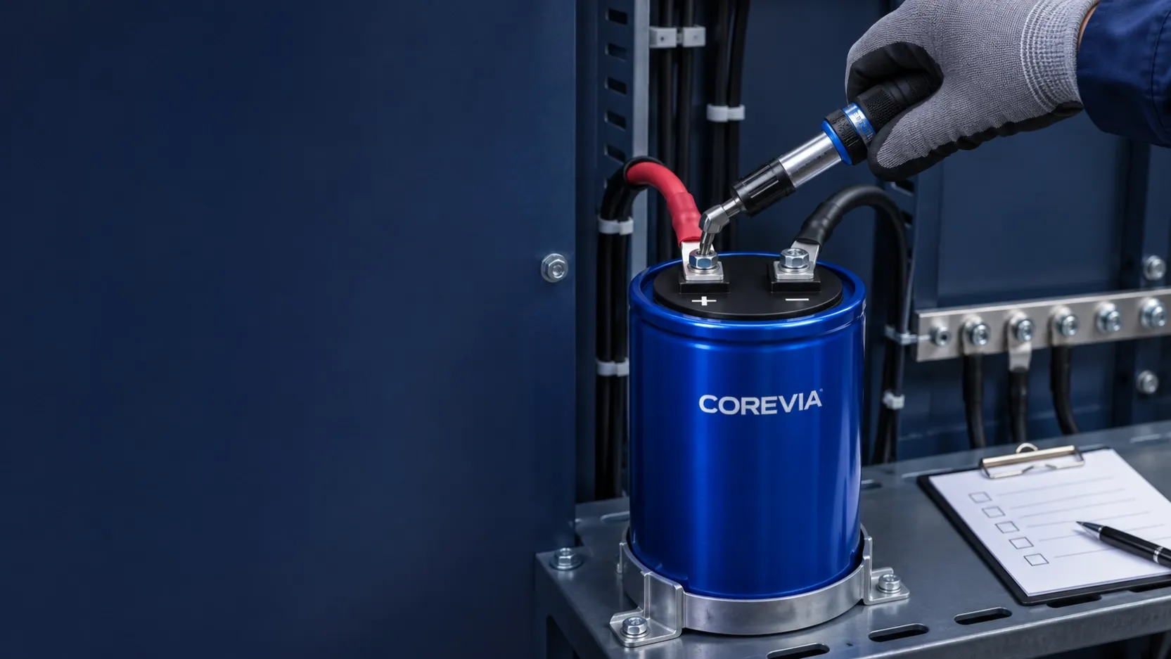
Do not force a snap-in aluminum electrolytic capacitor into PCB holes that do not match its terminal pattern. Stop assembly, compare the exact capacitor drawing with the board footprint, and resolve the mismatch before soldering. A part that appears to fit after pressure is applied may still have stressed terminals, a damaged seal, an incorrect seating position or reversed polarity.
What should you compare before insertion?
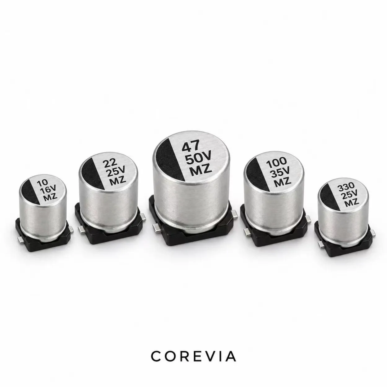
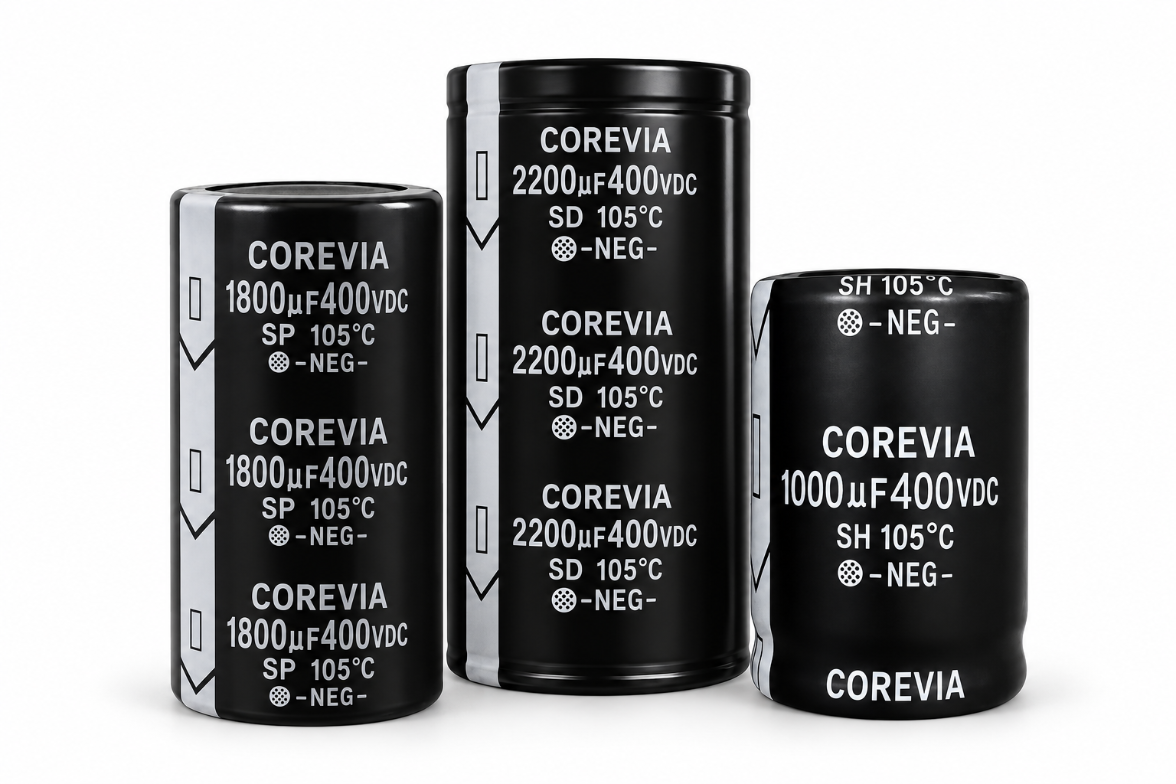
Start with the exact COREVIA series and part drawing, not a nominal case diameter or a generic footprint. COREVIA offers SP, SH, SS, SC, SF, SU, SD and SZ snap-in series. Their terminal layout must be checked against the selected part rather than assumed to be interchangeable. The COREVIA snap-in product family is the starting point for series selection; request the drawing for the actual part number before approving a PCB.
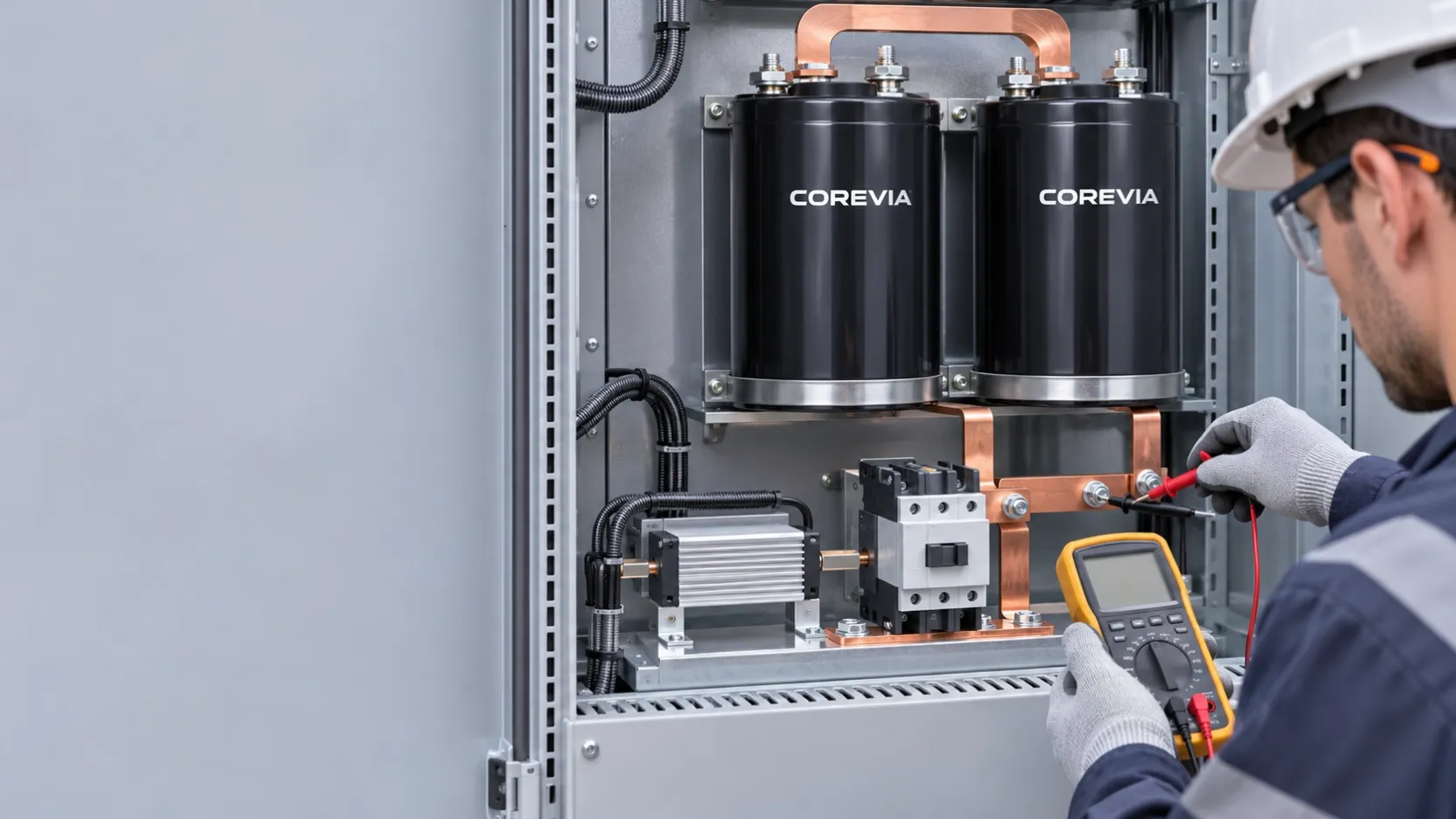
Measure the board and part in the same orientation. Compare hole-center spacing, terminal shape, terminal count, auxiliary or mechanical terminals if present, hole diameter, board thickness, case clearance and the positive/negative positions. The capacitor body should seat as intended without using the solder joints to pull the terminals into place. A footprint review should also account for the pressure-relief vent and nearby components.
| Check | Evidence to compare | Stop condition |
|---|---|---|
| Terminal pattern | Exact part drawing against PCB drill and copper artwork | A terminal must be pushed sideways to enter |
| Polarity | Part markings against PCB silkscreen and circuit netlist | Positive and negative positions do not match |
| Seating and clearance | Body position, board fit and neighboring parts | Body tilts, lifts or touches an obstruction |
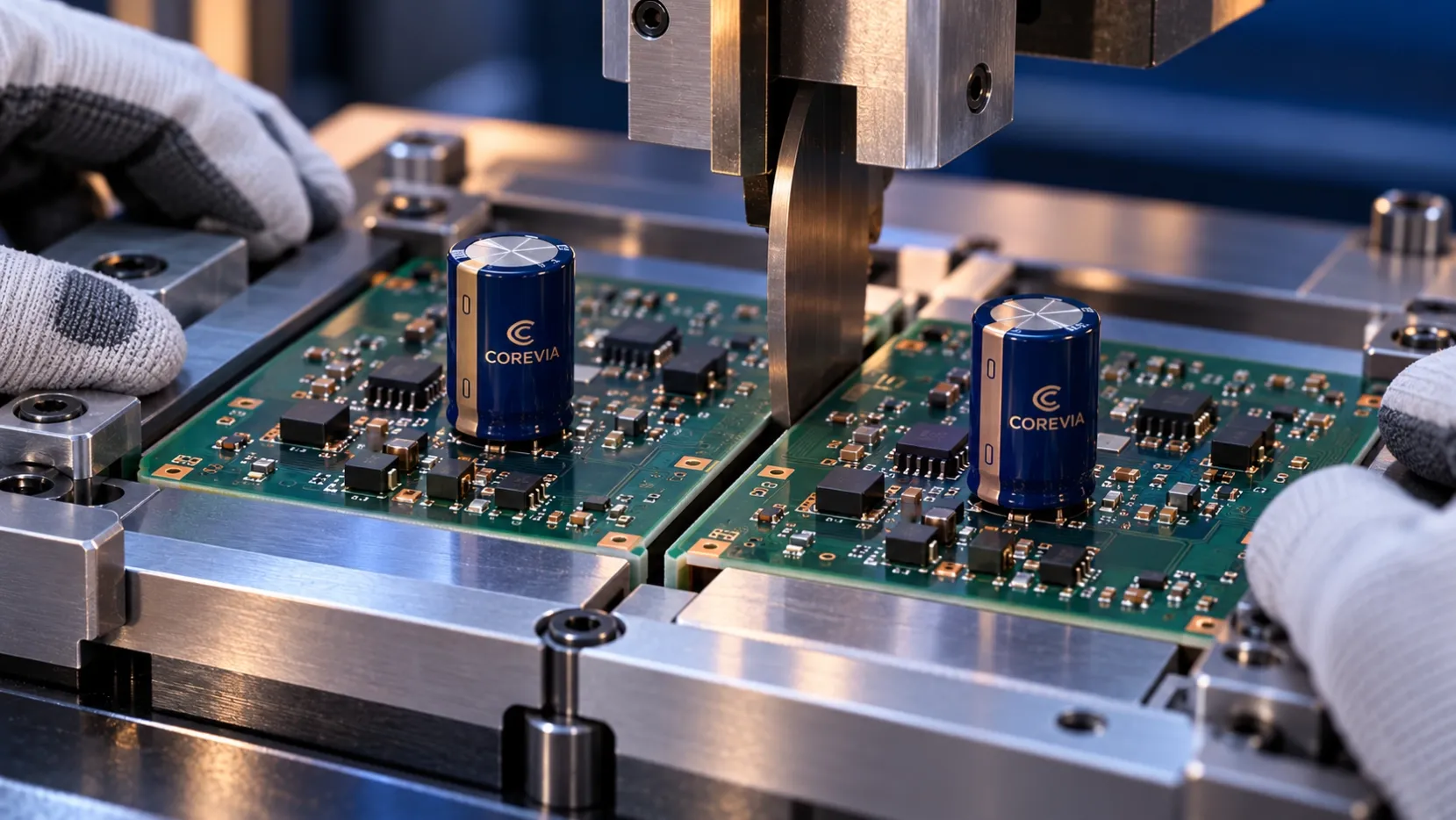
| Assembly process | Approved insertion and soldering method | Fixture or operator must apply excessive force |
What should you do when the pitch does not match?
Quarantine the affected assembly or parts and record the capacitor part number, PCB revision and measured hole pattern. Check whether the problem came from the wrong capacitor variant, an outdated drawing, a PCB fabrication issue or an assembly substitution. Do not treat a successful electrical reading immediately after soldering as proof that mechanically stressed terminals are acceptable.
Ask engineering to choose a controlled correction: source the capacitor with the approved terminal configuration, revise the footprint for a future board revision, or obtain a documented assessment of a proposed alternative. Do not bend rigid snap-in terminals or enlarge holes on the production line without a part-specific process approval. Forming allowances and sealing construction can differ between products, so a general rule from another part is insufficient for a COREVIA series.
What should buyers send for a COREVIA fit review?
Send the target voltage and capacitance together with the mechanical evidence. A useful request includes the existing capacitor part number, COREVIA series under consideration, PCB drill drawing or dimensioned footprint, terminal polarity, maximum case diameter and height, board thickness, assembly method and expected quantity. If the board is already built, include clear top and bottom photographs and the measured hole-center distances. This lets COREVIA review a specific physical interface alongside the electrical requirements, rather than guess from a photograph of the can.
For a replacement project, the mechanical envelope checklist can help organize the case, mounting and clearance checks. A footprint match is one part of approval; voltage, ripple current, temperature and endurance still need their own review.
FAQ
Can I use pressure to make the terminals enter the holes?
No. If the terminals do not enter and seat naturally, stop and compare the exact drawing with the PCB. Force can hide a dimensional or polarity error and can stress the terminal-to-seal interface.
Is the same can diameter enough to prove two snap-in parts fit the same PCB?
No. Case size alone does not establish terminal spacing, hole size, auxiliary terminal arrangement or polarity position. Compare the complete part drawing and board footprint.
Can I bend the terminals to compensate for a small mismatch?
Do not make that change by default. Ask for the exact COREVIA part drawing and an approved assembly assessment. If the terminal pattern is wrong for the board, selecting the correct configuration or revising the PCB is the clearer controlled solution.
Send the footprint drawing and target electrical requirements through COREVIA's contact page to request a snap-in series and fit review before the next production build.