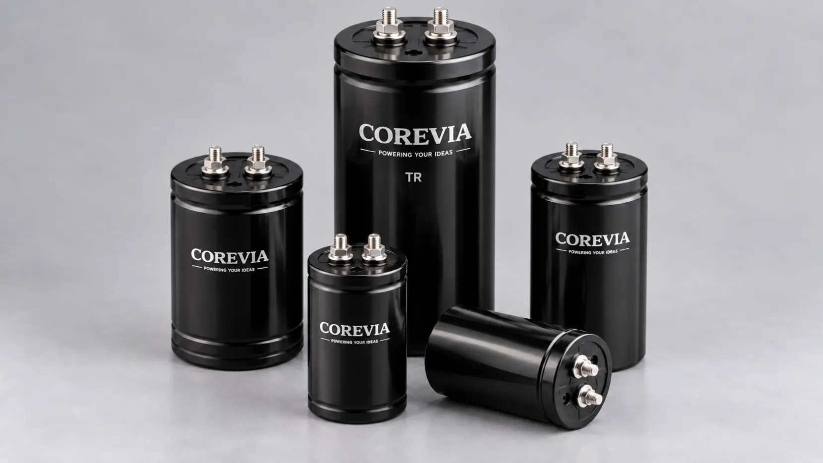
Will a Replacement Electrolytic Capacitor Fit? Check the Mechanical Envelope
Before replacing an aluminum electrolytic capacitor, compare its case envelope, terminal pattern, mounting and installed clearance. Use this COREVIA fit checklist.
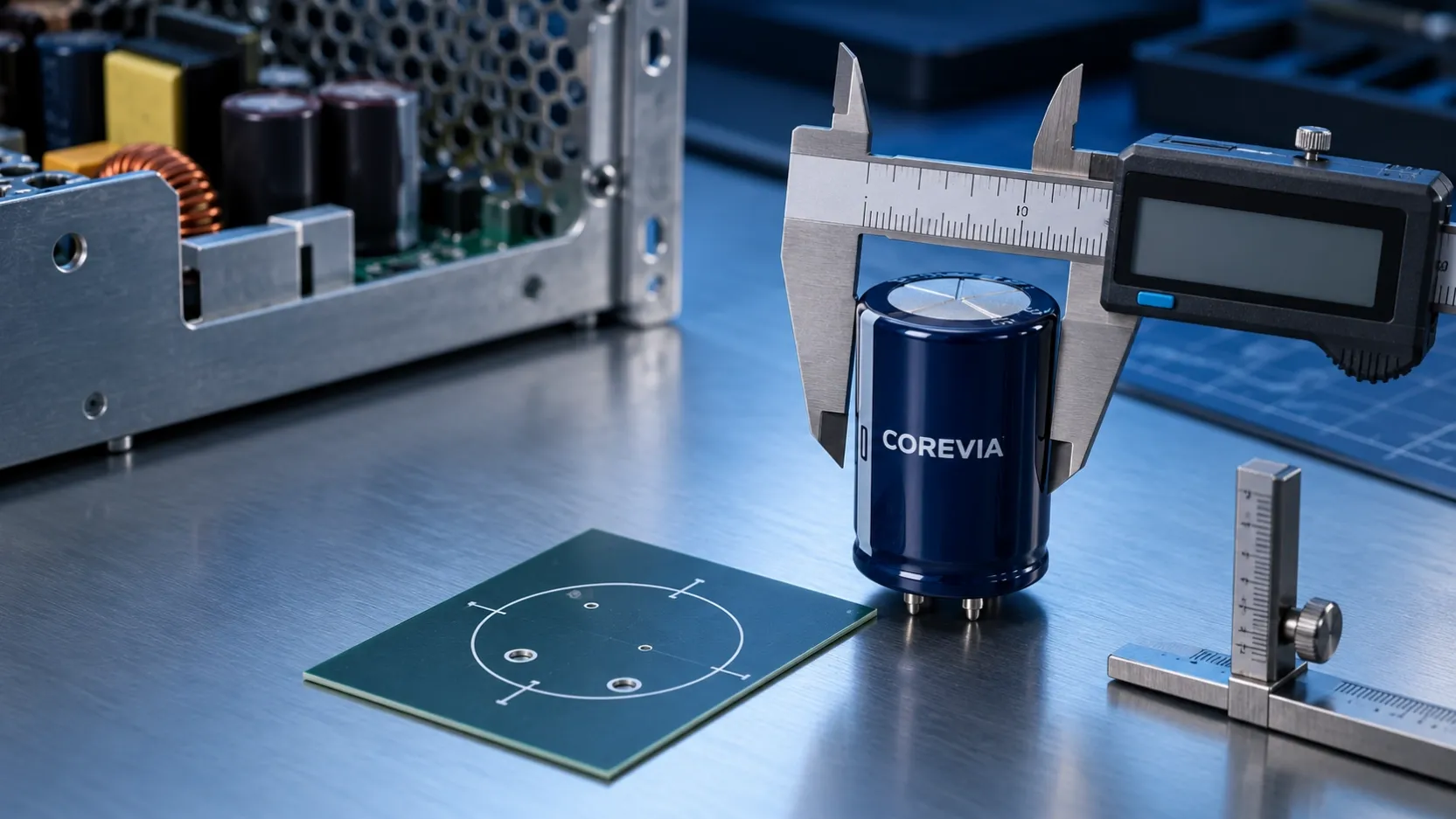
Short answer: A replacement aluminum electrolytic capacitor fits only when its maximum body envelope, terminal or lead pattern, mounting hardware, and installed clearance all match the actual assembly. Matching capacitance and voltage alone cannot confirm that it will fit a PCB or enclosure. Measure the existing assembly, then compare those measurements with the drawing for the exact COREVIA series and case size before ordering.
Which dimensions determine whether the capacitor fits?
Start with the available space in the finished product, not the nominal diameter printed in a catalogue. Measure the board hole pattern or busbar connection points, the distance to the enclosure lid, nearby components, cable routes and any mounting clamp. Then request the mechanical drawing for the proposed part. A body that clears the bare PCB may still interfere with a lid, a cable or a service tool after installation.
| Fit check | Measure in your assembly | Confirm on the proposed part |
|---|---|---|
| Body envelope | Maximum free diameter and installed height | Case dimensions and drawing tolerances |
| Connection pattern | PCB hole spacing and hole size, or busbar hole centres | Lead, snap-in pin or screw-terminal layout |
| Mounting | Clamp, bracket and board support position | Approved mounting method for the exact series |
| Clearance | Distance to lid, cables, insulation and adjacent parts | Required space around terminals and pressure-relief vent |
Record the dimensions in a sketch with a clear reference point, such as the PCB top surface. Include the enclosure or heat-sink position that limits the available space. This makes a supplier drawing comparison much more reliable than a photograph alone.
How does the terminal format change the fit check?
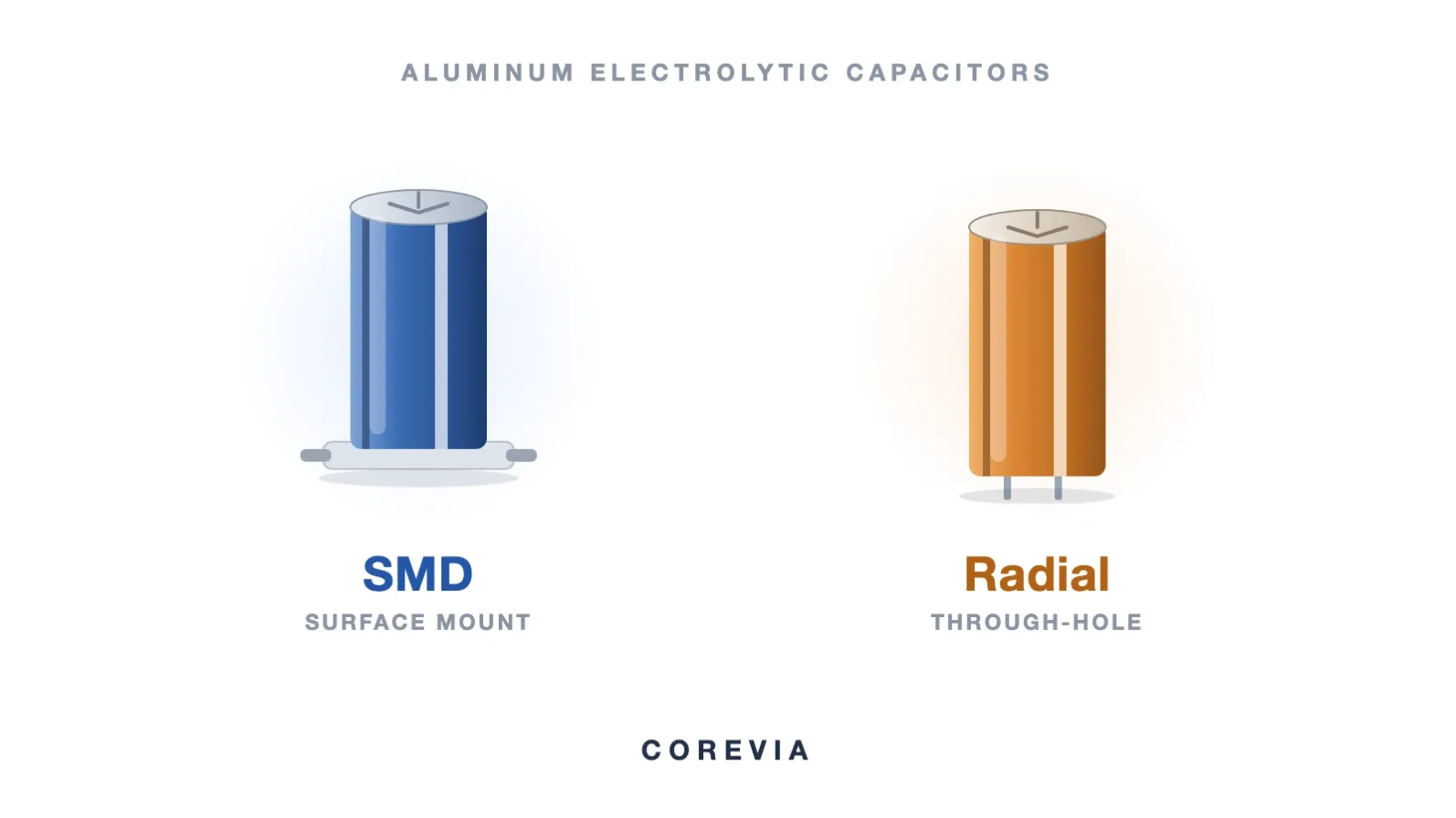
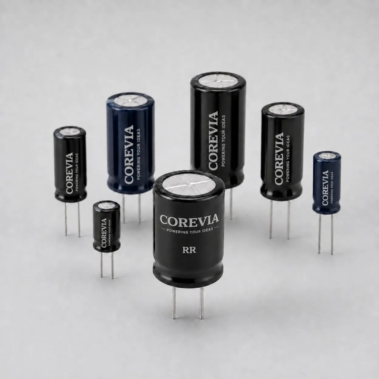
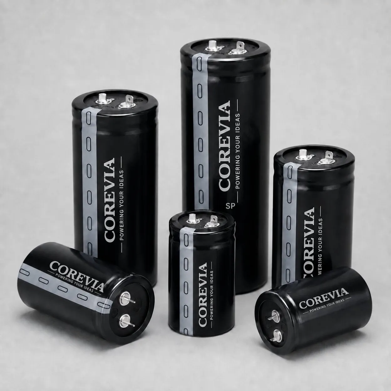
COREVIA supplies radial leaded, SMD, snap-in and screw-terminal aluminum electrolytic capacitor families. Each format needs a different mechanical comparison. A shared voltage and capacitance rating does not make the footprints interchangeable.
PCB-mounted radial, SMD and snap-in parts
For a radial part, compare lead pitch, lead diameter, polarity position, body diameter and height. For an SMD part, compare the land pattern, base dimensions and assembly height. For a snap-in part, compare every pin position with the PCB holes, including any mechanical support pin. Do not force a lead or pin to compensate for a mismatch; revise the part selection or the board layout instead.
Screw-terminal parts
Compare the terminal centres, connection orientation, mounting arrangement and space needed to assemble the busbar without loading the terminals sideways. Confirm the exact drawing and installation instructions before specifying hardware or tightening conditions. The enclosure also needs space for safe access during installation and inspection.
What should you send before requesting a replacement?
Send the existing capacitor marking or part number, the required electrical ratings, and a dimensioned photo or sketch of the available space. Add the board drawing or busbar layout, terminal polarity, mounting method and the location of the enclosure lid. If your design has a strict height or diameter limit, state the maximum allowed finished-assembly dimension, not only the size of the removed part.
COREVIA can review the relevant product family against those requirements and identify which exact series drawing should be checked. The electrical review still needs operating voltage, ripple-current profile, temperature and required endurance; mechanical fit by itself is not an approval of electrical suitability.
FAQ: Can I accept a taller capacitor if the diameter is smaller?
Only after checking the installed height against the enclosure and all nearby parts. A smaller diameter does not compensate for a lid or cable interference. Verify both dimensions on the exact candidate drawing.
FAQ: Can a part with the same voltage and capacitance use the same PCB footprint?
No. Lead spacing, snap-in pin layout and SMD land pattern depend on the specific part and case size. Compare drawings before approving a substitute.
Need a mechanical-fit review for an existing design? Send COREVIA your drawing and operating requirements so the proposed series can be checked for both physical fit and electrical suitability.