Sep 21, 2026Reliability Engineering
The Capacitor Bank Passes the Test. Is Every Capacitor Really Healthy?
Learn why an overall capacitance reading may hide one weak or disconnected capacitor in a parallel DC-link bank and how to inspect each branch properly.
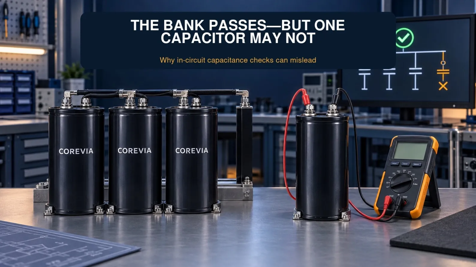
A technician measures the capacitance of a complete DC-link capacitor bank. The result falls within the expected range, so the bank is considered healthy. Yet the equipment still experiences DC-bus fluctuations, intermittent protection trips or unexplained shutdowns under load.
An acceptable total capacitance reading does not establish that every capacitor is healthy or that every branch is connected. A parallel bank must be assessed as both a group of components and a network of fuses, terminals, conductors and busbar joints.
Why the Complete Bank Can Appear Normal
A measurement across the bank terminals reflects the electrical network connected to those terminals. It does not identify the contribution of each individual capacitor. Other circuit paths can also influence an in-circuit reading, depending on the instrument and the equipment topology.
In a larger parallel bank, the loss of one branch may cause only a modest change in the total reading. Component tolerance, instrument accuracy, test frequency, temperature and the absence of a reliable baseline can make that change difficult to recognize.
This does not mean that a disconnected capacitor contributes capacitance. It means the remaining connected capacitors can produce a total that still looks plausible when compared with a broad acceptance range.
Capacitance Is Only One Part of the Assessment
A low-level capacitance test does not reproduce the bank's operating voltage, ripple-current spectrum or thermal conditions. It also does not, by itself, establish acceptable ESR, leakage current, insulation condition or connection integrity.
Compare measurements with the exact component specification and the equipment manufacturer's maintenance criteria. A total reading is useful for screening and trending, but it should not be treated as a certificate of health for every branch.
How One Capacitor Can Stop Contributing
Several different conditions can reduce or remove a branch's contribution:
- Significant capacitance loss caused by aging or previous electrical and thermal stress.
- Increased internal losses or internal connection damage.
- An open branch fuse, where individual branch protection is fitted.
- A loose, damaged or disconnected cable or terminal.
- A cracked conductor, damaged busbar joint or poor contact surface.
- A connection that becomes intermittent with vibration or temperature changes.
A high-resistance connection and a completely open connection are different faults. A resistive joint may generate local heat; an open branch may carry little or no current. Identify the actual condition before deciding that the capacitor itself needs replacement.
If a fuse has opened, investigate why it operated. Replacing or bypassing the fuse without identifying the cause can conceal the original problem. Use only the protection specified for the equipment.
Why Large Parallel Banks Are Harder to Diagnose
When one branch is lost, the remaining branches may carry a greater share of the ripple current, depending on the converter's operating conditions and the bank layout. The equipment may continue running while its thermal margin and available capacitance have been reduced.
The resulting symptoms may emerge only at higher load, during load changes or after the cabinet has warmed up. A satisfactory reading during a shutdown may therefore coexist with an operating problem.
Current sharing also depends on branch impedance and physical layout. For the related issue of unequal branch loading, see Why One Capacitor in a Parallel Bank Runs Hotter.
The Cold Capacitor Clue
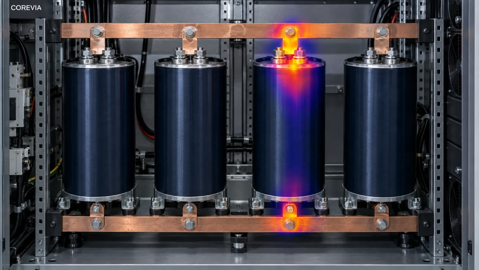
An abnormal capacitor is not necessarily the hottest unit. If its branch is disconnected, it may generate less internal heat and appear cooler than neighboring capacitors that are carrying ripple current.
An unusually cool unit is a clue, not proof of an open circuit. Differences in airflow, mounting position, nearby heat sources, surface emissivity and camera angle can also affect apparent temperature. A capacitor in an open branch may still be warmed by adjacent components.
Compare Both Hot and Cold Outliers
- Compare units at the same load and after a similar operating period.
- Record ambient temperature, cooling conditions and each capacitor's position.
- Distinguish heat concentrated at a terminal from temperature across the body.
- Note reflective surfaces and differences in surface finish that could distort thermal readings.
- Correlate a temperature outlier with isolated electrical tests and connection checks.
Thermal inspection during operation must follow the equipment's approved safety procedure and be performed by qualified personnel using suitable access arrangements. Do not open an energized enclosure or disturb live connections simply to obtain a thermal image.
A Practical Inspection Procedure
1. Isolate the Equipment and Verify Discharge
Follow the equipment manufacturer's shutdown, isolation and lockout procedure. Account for every possible energy source, including auxiliary supplies and backfeed paths.
Use the specified discharge method and a suitably rated instrument to verify a safe voltage before touching components. Check each capacitor or isolated branch: a disconnected capacitor may retain charge even when the main bus reads near zero. Allow for voltage recovery and repeat checks as required by the procedure. Never discharge a capacitor by shorting its terminals with a tool.
2. Photograph and Label the Connections
Before disconnecting anything, record:
- Each capacitor's position and branch identification.
- Positive and negative terminal orientation.
- Cable routing, busbar connections and fitted branch fuses.
- Part markings, rated voltage, capacitance and available date or lot codes.
- Existing damage, discoloration, leakage or disturbed connections.
Clear identification makes it possible to connect an individual measurement with the original thermal image and fault location.
3. Measure Each Capacitor Independently
Isolate each capacitor sufficiently to remove parallel measurement paths, following the equipment's service instructions. Do not assume a reading is independent merely because the main supply is disconnected.
- Measure capacitance under consistent, specified test conditions.
- Measure ESR or dissipation factor when suitable equipment and acceptance criteria are available.
- Record test frequency, instrument settings, temperature and measurement uncertainty where relevant.
- Compare each result with the exact component specification, previous measurements and neighboring units.
- Record outliers even when the overall bank reading appeared acceptable.
Leakage-current or applied-voltage testing requires a separate controlled procedure and appropriately rated, current-limited equipment. A handheld capacitance measurement cannot substitute for those tests. Do not apply an arbitrary test voltage to a suspect component.
4. Inspect Fuses, Terminals and Busbars
With the equipment isolated and discharge verified, check the complete connection path for each branch:
- Fuse condition and continuity, where fuses are fitted.
- Loose fasteners, damaged threads and signs of movement.
- Oxidized, contaminated, pitted or overheated contact surfaces.
- Cracked conductors, damaged cables and insulation deterioration.
- Correct assembly and terminal torque according to the equipment and component requirements.
Continuity alone may not reveal a joint that develops excessive resistance under load. Further connection-resistance testing should follow an approved method. Do not tighten terminals beyond their specified torque to compensate for a damaged joint.
5. Reassemble and Verify Operation
Restore the approved wiring arrangement, polarity, protection and mechanical supports. Complete the required pre-energization checks before returning the equipment to service.
Qualified personnel should then verify operation under the relevant load conditions. Where safe measurement arrangements exist, compare branch currents, temperature distribution and DC-bus behavior. Confirm that the original symptom has been resolved, rather than relying only on a new total capacitance reading.
What Information to Record
A useful inspection record connects component measurements with operating conditions:
- Equipment type, identification and capacitor-bank configuration.
- Capacitor position, branch number, ratings and service history.
- Total bank capacitance and individual measurements.
- ESR or dissipation-factor results, with test frequency and temperature.
- Fuse, cable, terminal and busbar condition.
- Thermal images showing hot and unusually cold units.
- Load, ambient temperature, airflow and operating time when images were taken.
- Normal DC-bus voltage, relevant ripple or transient observations and measurement conditions.
- Fault codes, shutdown timing and the operating event associated with the fault.
- Previous replacements and the corrective action taken for each finding.
Mark missing information as unknown. Measurements taken under different conditions should not be presented as directly comparable without explaining the difference.
When the Whole Bank Should Be Reviewed
Review the bank as a whole when several capacitors show divergent results, repeated branch failures occur, or all units share the same long service history and stressful operating environment.
Replacing a single component may be appropriate, but a new unit can have different impedance and aging characteristics from the remaining capacitors. Review electrical compatibility, current sharing, mounting, cooling and protection before approving the repair.
The decision to replace one capacitor or a complete bank should follow measured condition and equipment guidance. An open connection does not automatically justify replacing every capacitor, and a satisfactory total reading does not justify leaving a confirmed faulty branch in service.
COREVIA Application Support
For a capacitor selection or replacement review, share the capacitor markings, bank arrangement, operating voltage, ripple-current information, case dimensions, cooling conditions and the inspection results. Include the affected branch position and the timing of the equipment fault.
The most useful question is whether each capacitor and its connection path are performing their intended role under the actual operating conditions.
COREVIA
Aluminum Electrolytic Capacitor Solutions