Aluminum Electrolytic Capacitor Vent Clearance: What to Check Before Installation
Keep the pressure-relief vent unobstructed. Review enclosure height, cables, adhesive and mounting tolerances before approving an aluminum electrolytic capacitor layout.

Leave the pressure-relief vent of an aluminum electrolytic capacitor unobstructed, and confirm the required space from the exact part drawing or application instructions. A capacitor that fits under the enclosure lid is not automatically ready for installation: cables, adhesive, mounting hardware and assembly tolerances can reduce the space available for the vent to operate.
This guide helps engineers and buyers review mechanical fit before approving a COREVIA capacitor for a power supply, UPS or inverter. It focuses on vent access and clearance, rather than diagnosing why a capacitor has already vented.
1. Identify the vent before checking available space
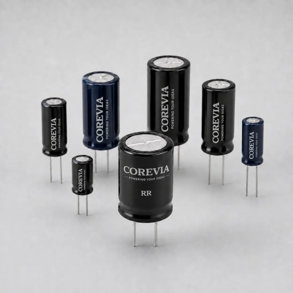
The pressure-relief vent is intended to reduce the risk of uncontrolled rupture when internal pressure rises during a malfunction. It is not a normal operating outlet. Its position and construction must be identified on the selected part; do not assume that every capacitor has the same vent arrangement.
Start the review with the part number, case drawing and installed orientation. Mark the vent location on the equipment layout, then identify the nearest lid, board, busbar or cable. For a vent facing a board or support plate, ask whether the mounting design provides the specified opening or unobstructed path.
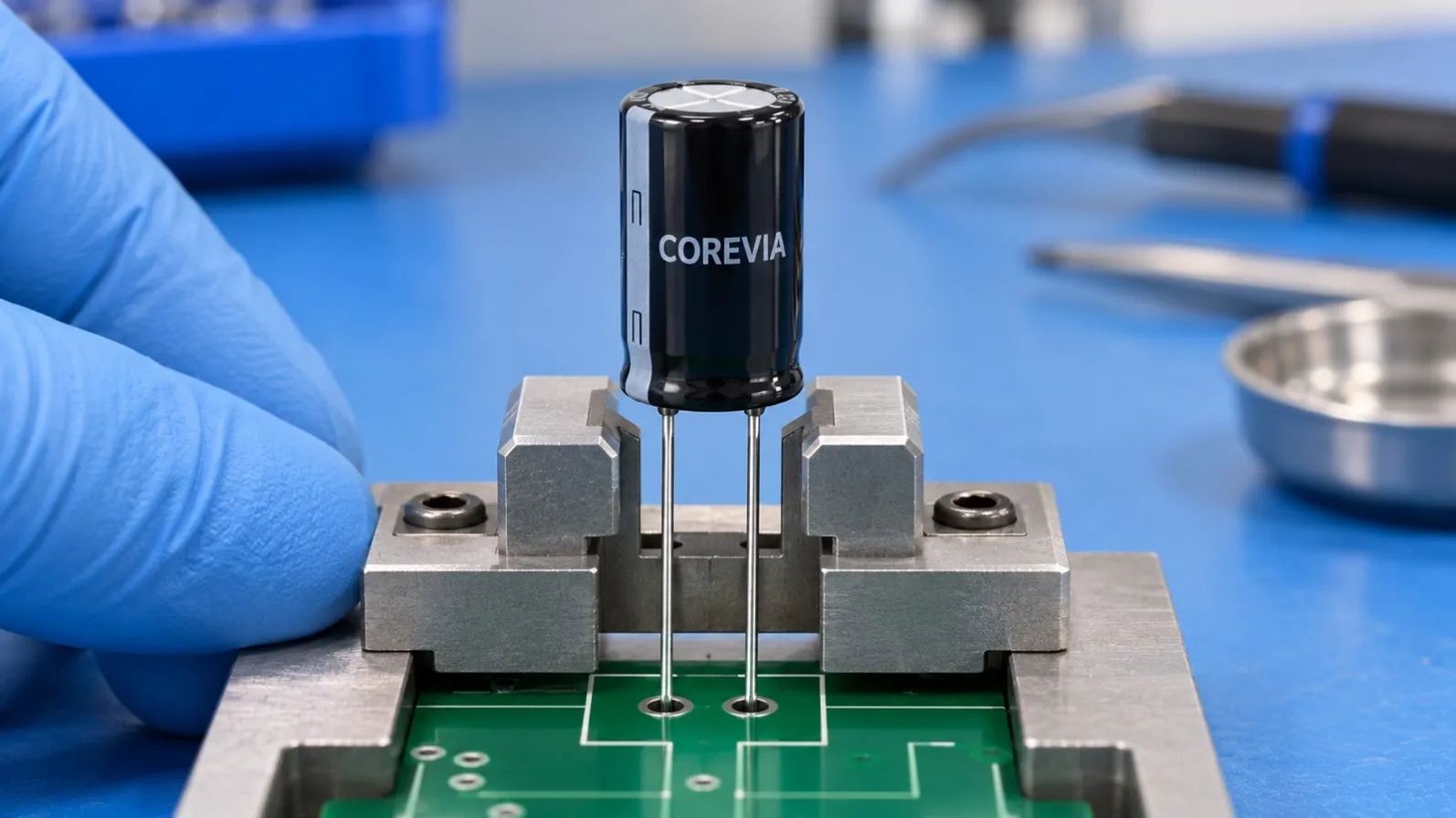
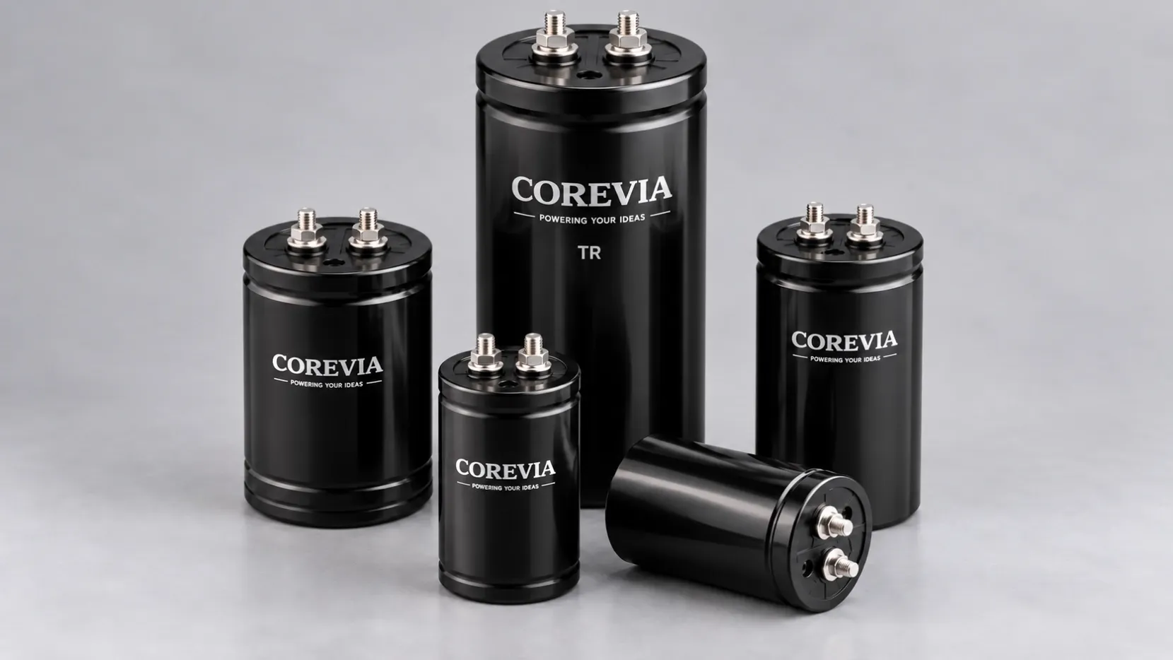
A photograph can help locate a visible vent, but it does not establish the required clearance. Use the applicable specification to define the acceptance limit.
2. Review the complete assembly, not only capacitor height
Use a layout check that includes every object around the vent. A nominal height comparison can miss a wire crossing the opening or an adhesive bead added later in production.
| Item to review | Question before approval | Evidence to keep |
|---|---|---|
| Enclosure lid or adjacent board | Is the minimum installed vent clearance maintained? | Dimensioned section view with tolerances |
| Cables and harnesses | Can routing, movement or assembly variation place a cable over the vent? | Routing drawing and final assembly photo |
| Adhesive or potting | Does the proposed material or process cover or restrict the vent? | Material and process details for review |
| Clamp, bracket or busbar | Does the hardware obstruct the vent or require an unapproved orientation? | Mounting drawing and orientation requirement |
| Service replacement | Does the replacement preserve the approved vent position and envelope? | Comparison against the released part drawing |
A simple tolerance example
Suppose a layout has 4 mm of nominal free space. If the permitted combination of capacitor height, mounting position and lid variation can consume 1.5 mm, only 2.5 mm remains in that condition. The calculation is 4 − 1.5 = 2.5 mm. These are illustrative dimensions, not a COREVIA clearance specification. Compare the resulting minimum space with the requirement for the exact part.
The useful design question is therefore: “What is the smallest available clearance in the permitted assembly?” Record the reference surfaces and measurement direction so production and inspection teams assess the same feature.
3. Confirm the requirement for the exact COREVIA part
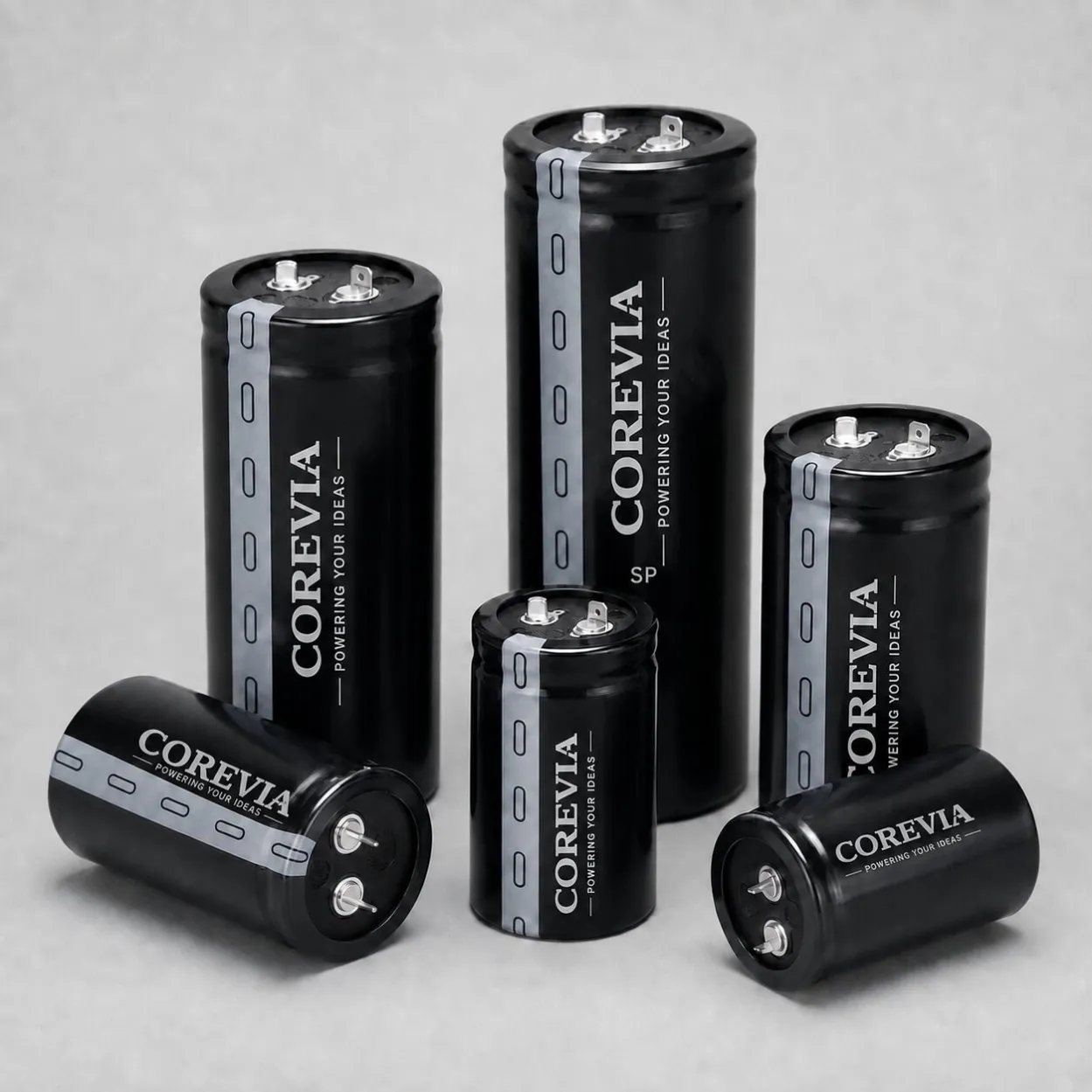
COREVIA's snap-in capacitor portfolio includes SP, SH, SS, SC, SF, SU, SD and SZ series. A shared terminal format does not establish a common case height, vent position or mounting requirement. Review the selected series and complete part number rather than applying one family-wide assumption.
For example, the product family page identifies SP as a standard series and SZ as an extended-endurance series. Those descriptions help narrow electrical selection, but neither substitutes for the mechanical drawing of the ordered part. If you are changing series or dimensions, repeat the vent-clearance review even when capacitance and rated voltage remain unchanged.
For screw-terminal capacitors, include the bracket, terminal connections and installed orientation in the drawing review. Do not select a universal clearance from an unrelated design. If the applicable COREVIA drawing does not state the needed vent dimension or orientation, request confirmation before releasing the layout.
What to send for a focused review
- COREVIA series and complete part number, or the proposed electrical requirements.
- Case dimensions and a section view showing the lid, PCB, support plate and vent position.
- Minimum available space after the relevant dimensional tolerances are included.
- Cable routing, clamps, busbars, adhesive and potting details near the capacitor.
- Installed orientation, local operating temperature and equipment application.
4. Make vent access part of the assembly release check
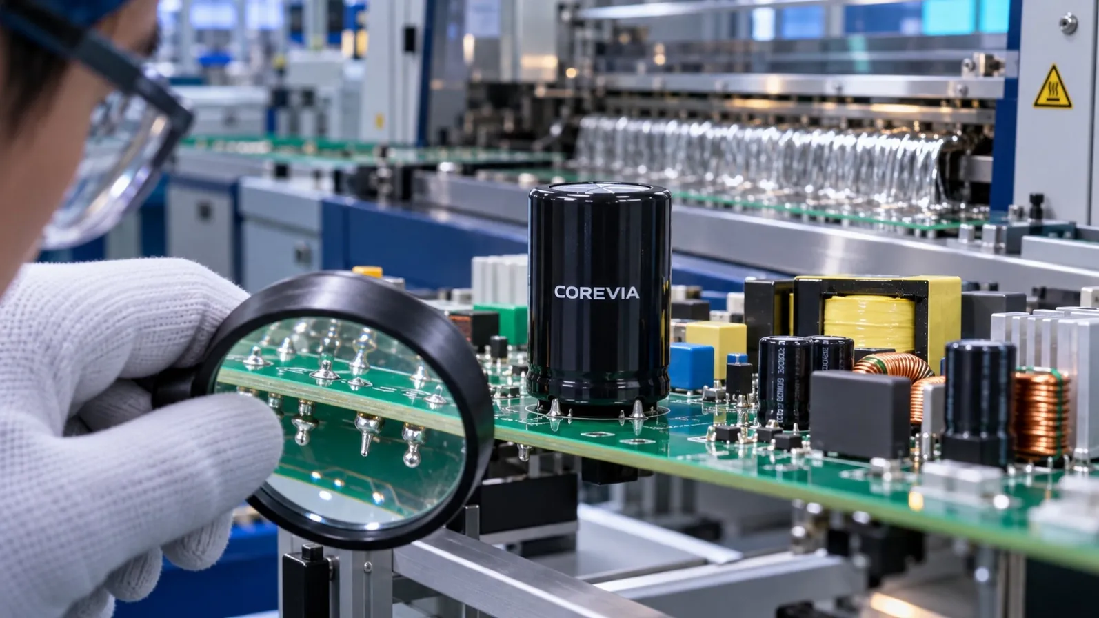
Compare the finished assembly with the approved layout. Check that production routing, support hardware and added materials preserve the reviewed space. Keep a clear assembly photograph and record the drawing revision used for approval.
This is a mechanical review, not a recommendation to trigger a vent as an incoming inspection test. Any specialized fault testing belongs within an approved equipment qualification procedure. If a vent has already opened, investigate the electrical and thermal cause before restarting; see the separate guide on why aluminum electrolytic capacitor vents open.
FAQ
Can I use one minimum clearance for every capacitor?
Use the requirement for the exact part and mounting arrangement. Case diameter, vent construction and orientation can differ.
Is an open gap above the can enough?
Check where the actual vent is located and whether anything crosses or restricts its operating path. A gap at the wrong end does not answer that question.
Can adhesive secure the capacitor near the vent?
Submit the proposed placement and process for review. Do not assume that an adhesive application is acceptable if it covers or restricts the vent.
What should purchasing include in a replacement request?
Provide the original part drawing, installed orientation and available envelope as well as the electrical requirements. This helps prevent a mechanically unsuitable substitution.
Next step: Send COREVIA your part number and installation drawing to confirm the mechanical information needed before approving your capacitor layout.