Oct 13, 2026Application Guides
Snap-In Capacitors and Wave Soldering: What to Check
Snap-in capacitor looks fine after wave soldering but fails inspection later? Check the solder profile, body exposure, mounting fit and test data.
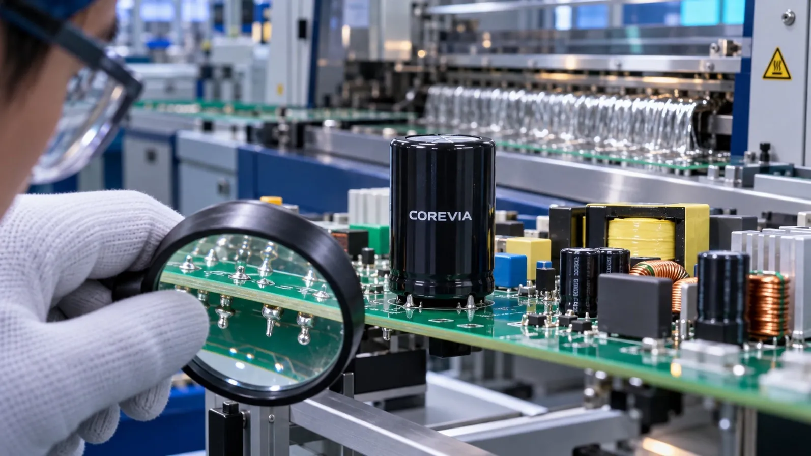
The capacitor looked fine when it went onto the PCB. After wave soldering, the finished UPS or inverter board fails inspection. Is the capacitor defective? Before rejecting the part, check what happened to it during assembly.
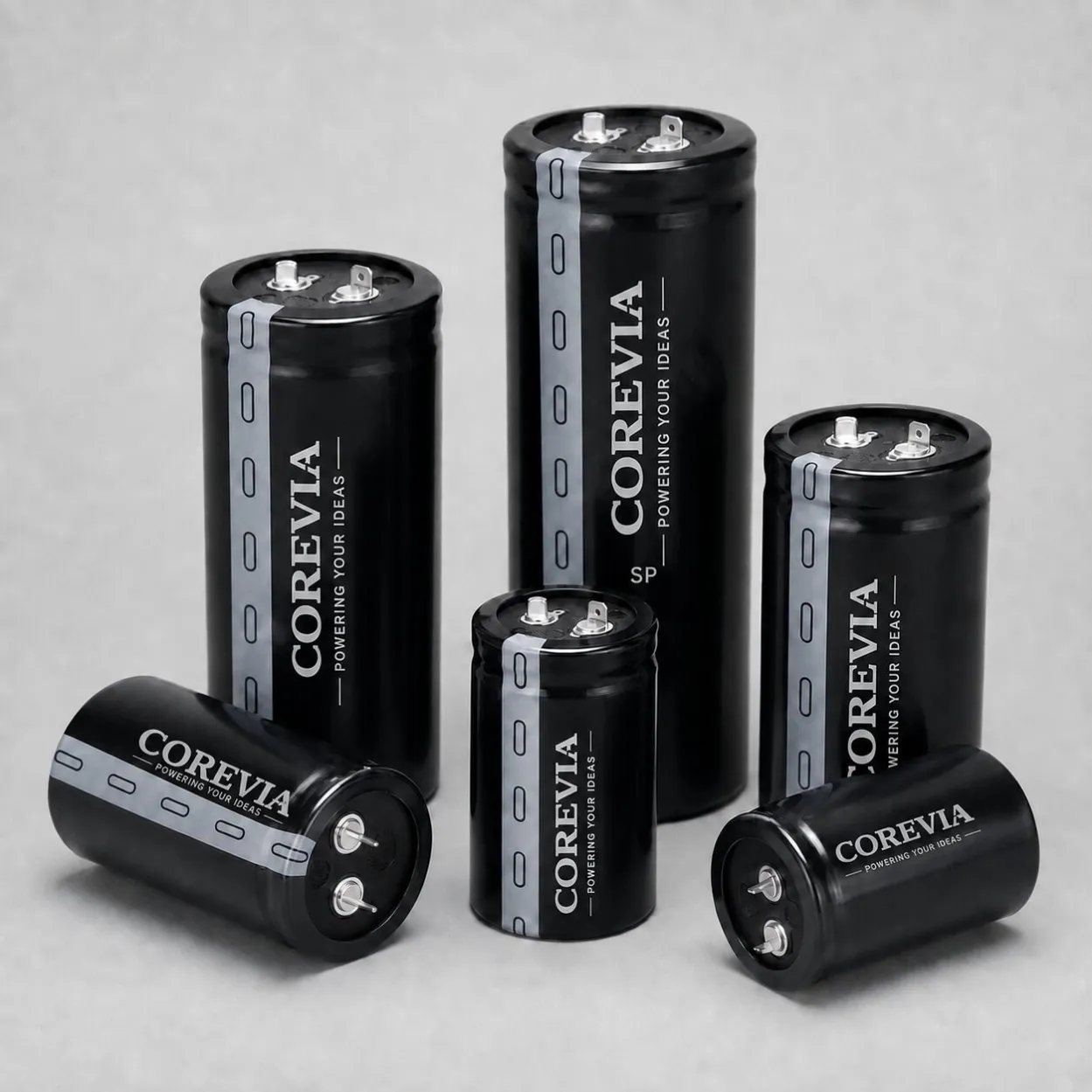
A snap-in aluminum electrolytic capacitor is soldered at its terminals. Its can and rubber seal should not be immersed in the solder wave. The allowed process depends on the exact capacitor series and the manufacturer’s soldering instructions, so a setting that works for another component is not automatically suitable here.
Why appearance can mislead
A capacitor can look normal after soldering while its terminals and seal have experienced more heat than the approved process allows. A poor joint can also cause an intermittent connection without any visible damage to the can. When a board later fails a functional test, the symptom alone does not identify which of these happened.
Start with the real board and the real profile
Ask for the measured preheat and wave-solder conditions at the capacitor location, including board orientation, exposure time and any repeat passes. Check whether the capacitor body was kept clear of the solder bath. Use the limits for the exact COREVIA series and case size; do not copy a generic temperature and time from another datasheet.
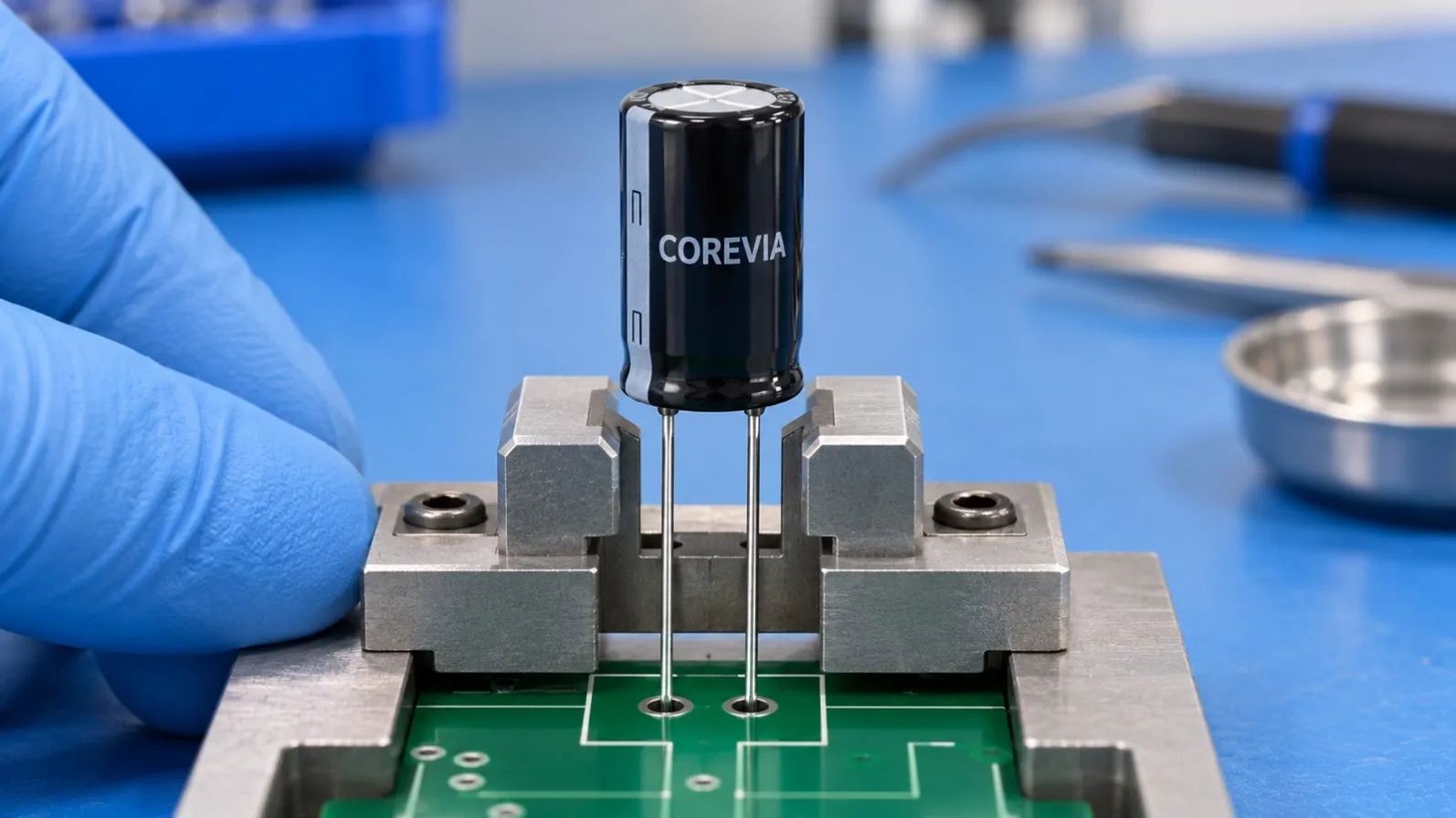
Then inspect the terminal joints on the underside of the board. Look for incomplete wetting, a cracked or disturbed joint and any movement of the capacitor during cooling. Check that the PCB hole pattern matches the terminal drawing. Forcing a snap-in capacitor into an unsuitable footprint adds mechanical stress before soldering even begins.
A practical way to separate the causes
Compare measurements at three points: an unused capacitor from the same lot, a capacitor immediately after assembly and a part removed from a board that failed test. Use the same test method and conditions for all three. Record capacitance, leakage current and ESR only after following the applicable test procedure; one quick reading does not establish the cause.
If unused parts are normal but results change after assembly, review solder exposure, board handling and joint quality. If only particular PCB positions fail, compare the local heating and solder contact at those positions. Keep the board, process record and samples together so the supplier can review the evidence.
What to send for a technical review
Send the capacitor part number and series, PCB layout around the terminals, solder profile recorded at the capacitor position, photos of both sides of the joint, the number of solder passes and the before-and-after measurements. This gives the engineer a much better starting point than a photo of an intact can and a note saying “capacitor failed.”
For UPS, inverters and industrial power supplies, a reliable capacitor choice includes the assembly process. Confirm the soldering and mounting conditions before production, then verify them on the actual board.
COREVIA — Industrial Aluminum Electrolytic Capacitor Solutions
Email:[email protected]
Whatsapp:861771262062