Sep 8, 2026Reliability Engineering
Why Aluminum Electrolytic Capacitor Bottom Vents Open
Learn why an aluminum electrolytic capacitor’s bottom pressure-relief vent opens and how to investigate overvoltage, reverse polarity, ripple current, heat and aging.
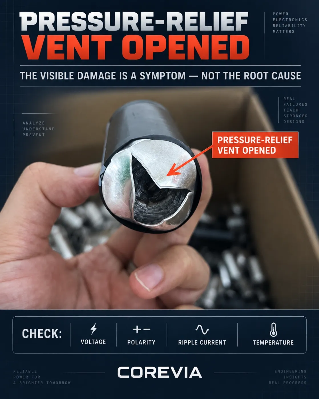
When the base of a large aluminum electrolytic capacitor opens and the winding becomes visible, the first reaction is often: “The bottom broke down.” That description is understandable, but technically incomplete.
If the aluminum case has separated along its factory-scored pattern, the pressure-relief vent has operated. This confirms that pressure inside the capacitor rose beyond the vent’s opening threshold. It does not prove that the electrical fault started at the bottom.
What the Photo Actually Shows
Wet aluminum electrolytic capacitors contain electrolyte and a tightly wound internal element. Under abnormal electrical or thermal stress, rapid heating and electrochemical reactions can generate gas or vapor. As the internal pressure rises, the scored section of the case is designed to open and release that pressure.
The visible opening is therefore the final failure mode—not the root cause. A dark exposed winding alone is also not enough to confirm carbonization or locate the original breakdown point. That requires controlled inspection of the internal element.
Once the pressure-relief vent has opened, the capacitor is permanently damaged and must not be energized or reused.
The Most Likely Causes to Investigate
1. Reverse Polarity or Negative Voltage
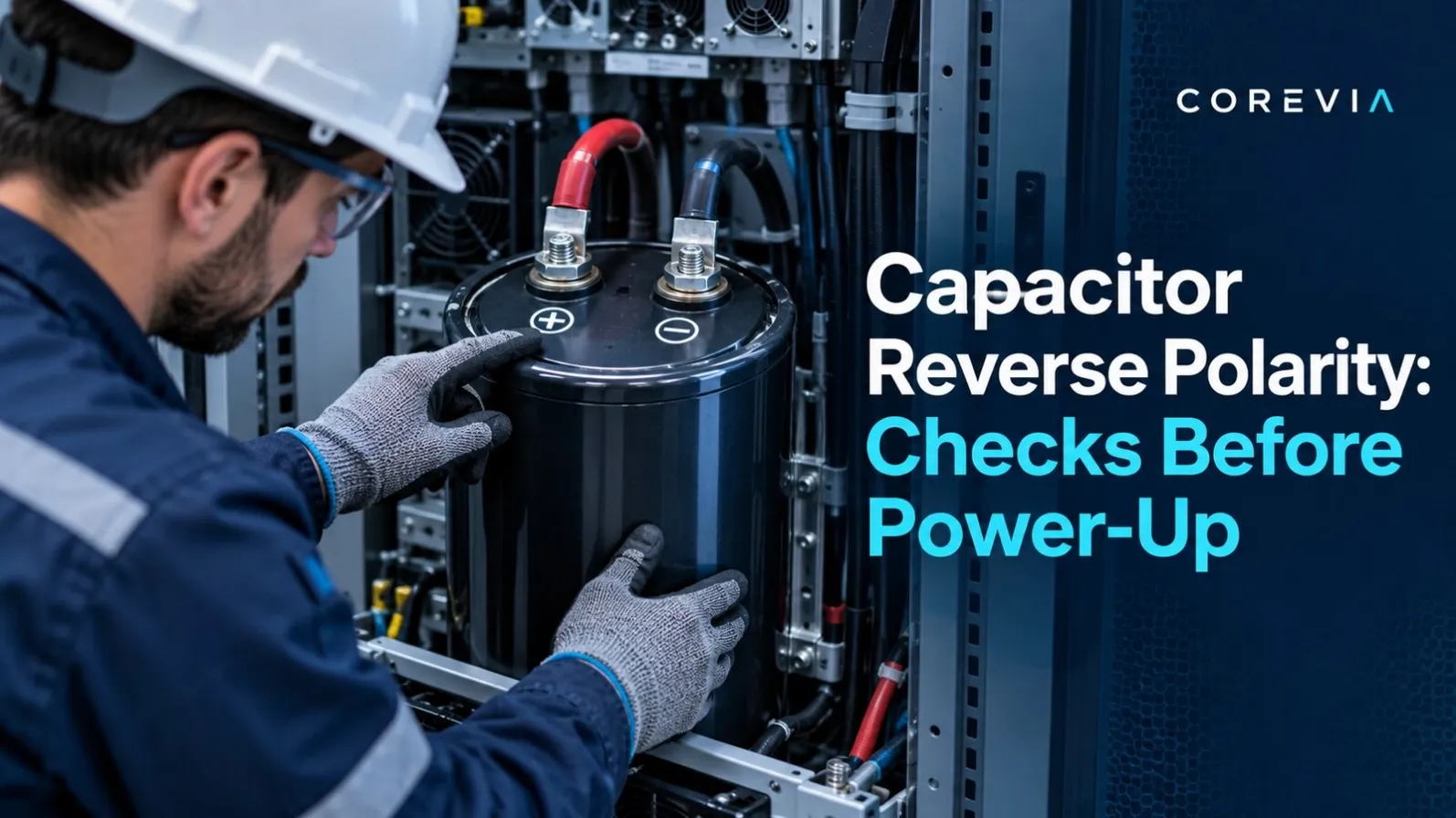
Aluminum electrolytic capacitors are polarized components. Incorrect wiring, a circuit fault or a negative voltage excursion can damage the dielectric oxide layer, increase leakage current and create rapid internal heating. When the failure occurs within seconds or minutes of power-up, polarity should be one of the first checks.
2. Overvoltage and Transient Peaks
The normal DC reading may appear acceptable while start-up, shutdown, regenerative operation or load changes produce short voltage peaks above the capacitor’s rating. The actual voltage must be measured directly across the capacitor terminals during all operating states—not only under steady load.
3. Excessive Ripple Current
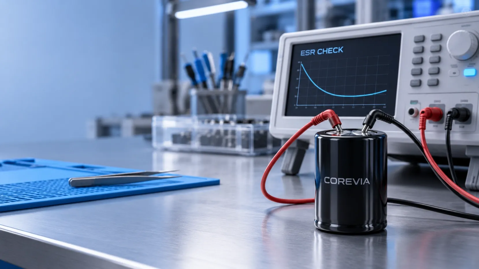
Ripple current flowing through the capacitor’s ESR produces internal heat. If the actual RMS ripple current is above the permitted value, or if frequency correction and operating temperature are not considered, the element may overheat. Insulation can deteriorate, leakage may increase and internal pressure can eventually open the vent.
In parallel capacitor banks, unequal busbar or PCB impedance can also concentrate more ripple current in one capacitor even when the calculated total current appears acceptable.
4. High Temperature or Poor Cooling
Ambient temperature is only part of the thermal picture. Nearby semiconductors, heat sinks, airflow restrictions and the capacitor’s own ripple-current heating all affect its real operating temperature. The investigation should include the capacitor surface temperature and the hottest local area, not just the cabinet temperature.
5. Unequal Voltage Sharing in Series Banks
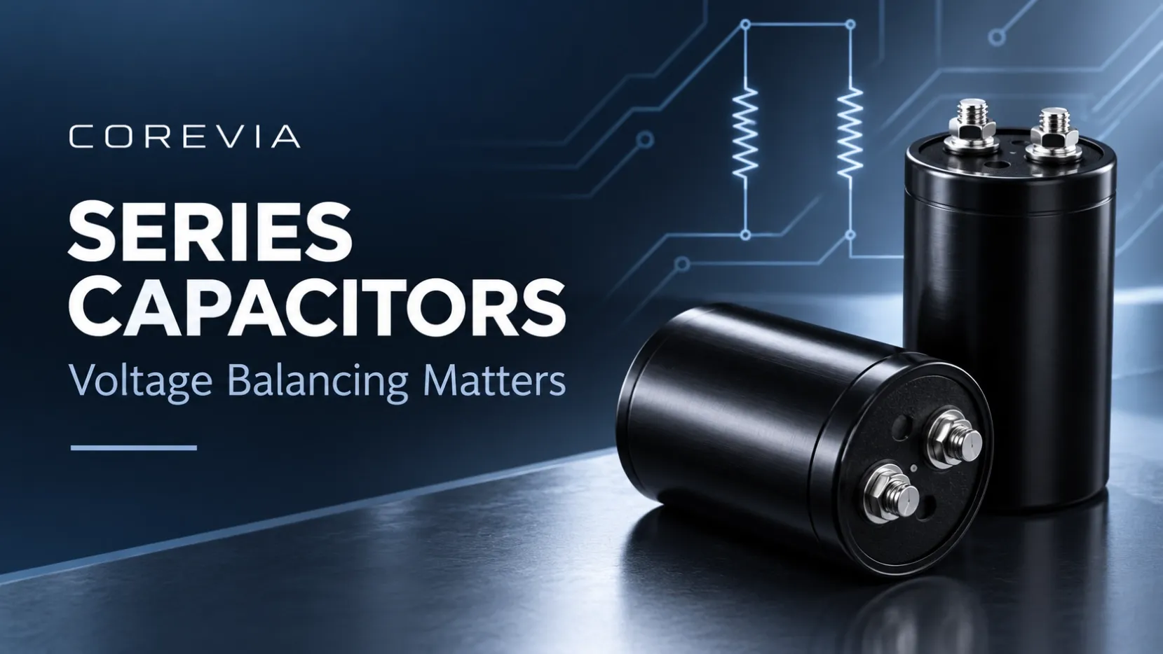
When capacitors are connected in series, differences in leakage current can cause unequal voltage distribution. One capacitor may be overstressed even when the total DC-link voltage appears normal. Balancing components and the voltage across each individual capacitor should be verified.
6. Aging, Storage History or an Individual Defect
Long operating time can increase ESR and internal temperature. Long-term storage—especially at elevated temperature—can increase leakage current until the dielectric is properly reformed. If only one capacitor fails while identical units under the same conditions remain normal, an individual component defect, mounting stress or manufacturing issue should also be considered. A photograph alone cannot distinguish these possibilities.
Failure Timing Gives Important Clues
• Failure immediately after power-up: check polarity, wiring, inrush conditions and overvoltage first.
• Failure only at high load: focus on ripple current, current sharing and cooling.
• Failure after long service: investigate aging, ESR increase and thermal history.
• Failure on first start after long storage: examine leakage current and reforming requirements.
• One failed unit in a capacitor bank: compare individual voltage, current, temperature, ESR and lot information.
Data Needed for a Reliable Root-Cause Conclusion
A responsible failure analysis should collect:
• The complete capacitor model, rated voltage, capacitance and lot code
• The circuit position and application, such as a UPS, inverter, industrial drive or energy-storage converter
• DC voltage and peak waveform during start-up, full load, load changes and shutdown
• Actual RMS ripple current and its operating frequency range
• Capacitor surface temperature, ambient temperature and cooling conditions
• Series or parallel configuration, balancing components and bus layout
• Operating hours, storage history and the number of failed units
• Comparison data from failed and healthy samples
Engineering Conclusion
From the external appearance, we can conclude that the pressure-relief structure opened because internal pressure became excessive. We cannot responsibly conclude from the photograph alone whether the initiating cause was overvoltage, reverse polarity, excessive ripple current, heat, aging or an individual defect.
The visible rupture is the symptom. The operating data reveals the cause.
COREVIA supports aluminum electrolytic capacitor selection and failure-condition review for UPS systems, inverters, industrial drives, energy storage and other power-electronics applications.