How Do You Check an SMD Electrolytic Capacitor PCB Footprint Before Production?
Before releasing a PCB, compare the SMD electrolytic capacitor land pattern, polarity and body clearance with the exact COREVIA part drawing and assembly process.
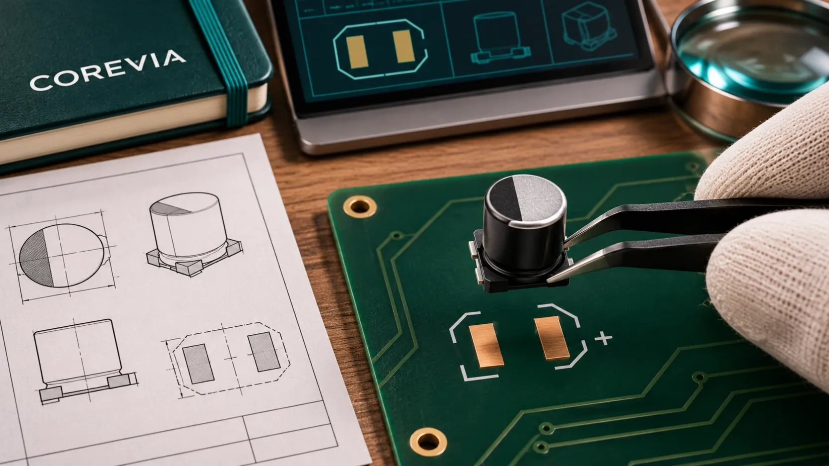
Before releasing a PCB for an SMD aluminum electrolytic capacitor, compare the board footprint with the drawing for the exact COREVIA part: terminal geometry, land spacing, polarity orientation and body clearance must all agree. A matching capacitance and voltage rating do not establish that a part will solder correctly onto an existing footprint. Resolve any mismatch in the CAD library and check a first assembly before volume production.
Which COREVIA drawing should drive the footprint?
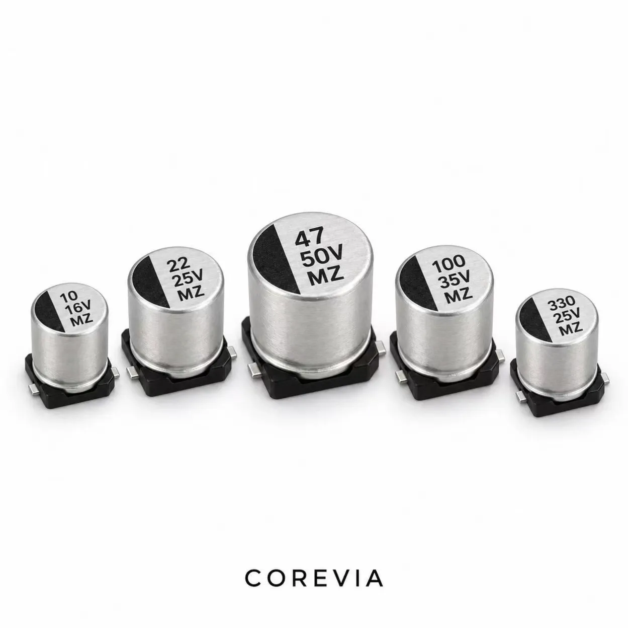
Identify the full part number and series, then obtain its current mechanical and mounting information. COREVIA lists SMD aluminum electrolytic capacitor families including MS, ML, MT, MZ and MM; the family name alone does not define one common land pattern. Confirm the can diameter, height, base outline, terminal arrangement and recommended board land dimensions for the actual part. Do not copy a footprint from another size merely because the nominal electrical ratings match.
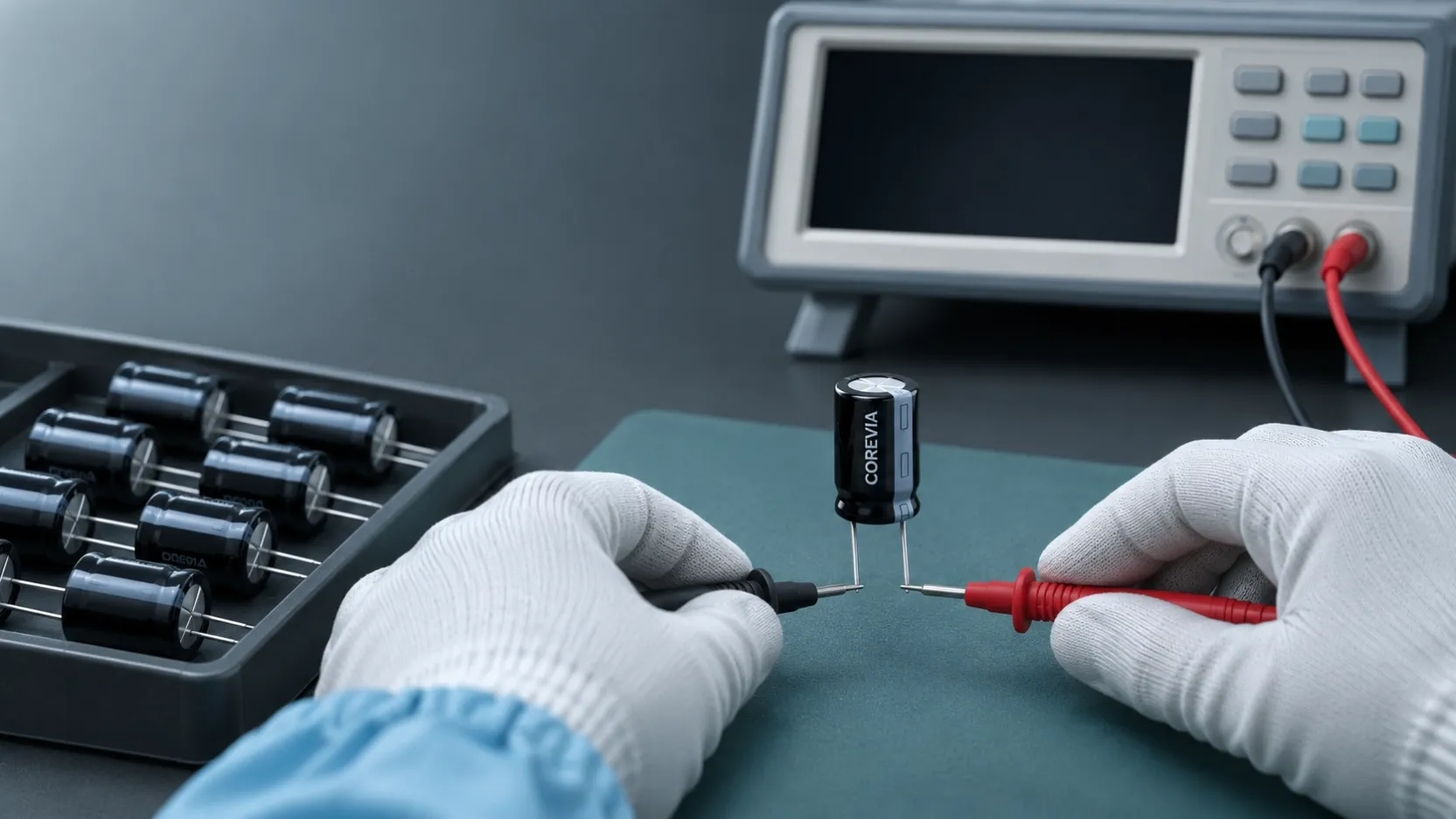
Record the drawing revision alongside the PCB library revision. If the part-specific land pattern is unavailable, request it before freezing the PCB. The illustration on this article is conceptual and is not a dimensional PCB drawing.
What should the PCB designer compare?
Overlay the component drawing on the proposed footprint at the same scale. Check that each terminal lands on the intended copper area and that the pad gap and solder mask follow the approved drawing and board fabrication rules. Check the polarity mark on the capacitor against the PCB silkscreen and schematic net. Also inspect the body courtyard for neighboring parts, enclosure walls and placement-tool access. A footprint review should include the actual assembly and inspection process, not only a CAD screenshot.
| Footprint review item | Question to resolve | Evidence to keep |
|---|---|---|
| Exact part and drawing | Is this the right COREVIA series and case size? | Part number and drawing revision |
| Terminal and pad geometry | Do both terminals align with the recommended lands? | Dimensioned footprint comparison |
| Polarity | Do component, silkscreen and circuit nets agree? | Annotated placement view |
| Body and process clearance | Can the part be placed, soldered and inspected? | Assembly drawing and first-article photo |
How should the footprint be approved before production?
Have the electrical and PCB layout owners review the same part number and drawing. Check the exported fabrication and assembly files, because a correct library symbol can still be mirrored or rotated in a placement file. For a new or changed footprint, build a small first article, inspect the terminal-to-land alignment and solder joints, and document any correction before releasing volume boards. Where vibration or mechanical loading matters, evaluate the complete mounted assembly against the application's requirement; pad dimensions alone do not establish reliability.
If the part supplied differs from the approved drawing, hold the substitution for engineering review. Send COREVIA the PCB footprint, target part number and available board space so the part and drawing can be checked together.
FAQ: SMD capacitor footprints
Can I reuse the footprint from a capacitor with the same voltage and capacitance?
Only after checking the mechanical and land pattern dimensions for the exact replacement. Electrical ratings do not prove footprint compatibility.
Is the PCB polarity mark enough for assembly?
Check the actual component marking, placement orientation, silkscreen and schematic nets together. A clear mark on one layer cannot correct a mirrored footprint or placement file.
Do I need a first article if the CAD drawing looks correct?
A first assembly is a useful final check for a new or changed footprint because it reveals placement, soldering and inspection issues that a drawing may not show.
Review the COREVIA SMD capacitor families, then send COREVIA your part number and PCB drawing before approving the footprint for production.