Application Guides
How Do You Size a COREVIA Supercapacitor for a Brief Power Interruption?
Size a COREVIA supercapacitor for controller hold-up by checking load energy, usable voltage, ESR and the exact cell data before validation.
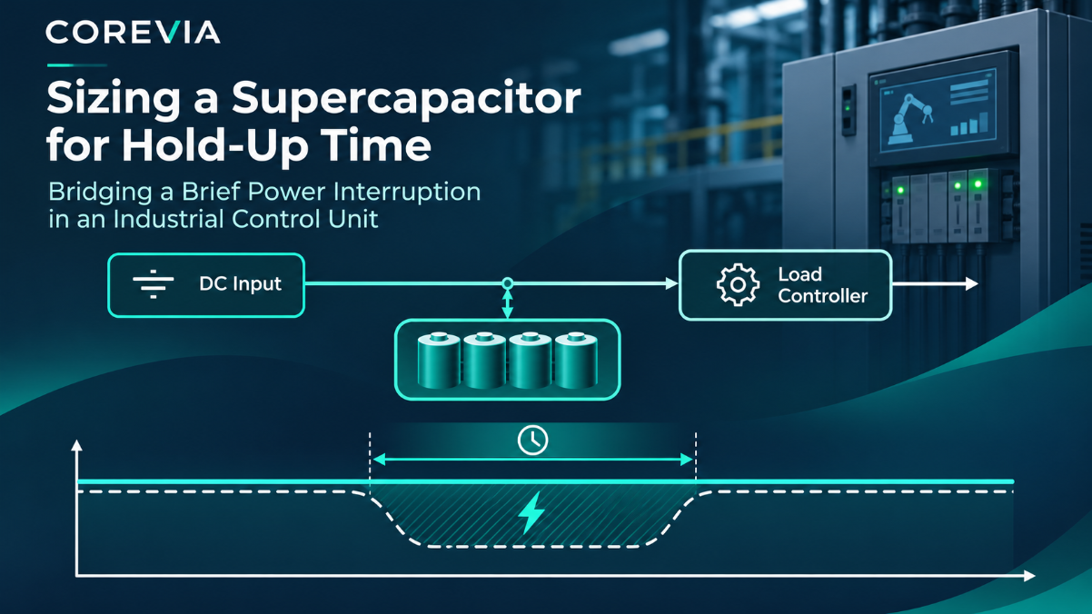
To size a COREVIA supercapacitor for a short power interruption, start with the load energy and the usable voltage window, then check ESR, charging and the exact cell data. A capacitance number alone does not tell you whether an industrial controller will stay alive: the load must still receive its minimum operating voltage at the end of the interruption.
What does the controller need during the interruption?
Record the controller's measured input power or current throughout the interruption, the required hold-up time, the lowest input voltage at which it operates, and the voltage available to charge the storage bank. Measure the real start-up and shut-down sequence as well as steady operation. A controller that only needs to retain memory may have a different load profile from one that must keep an output energized.
Define the power path before choosing a cell. A DC-DC converter can use part of the declining supercapacitor voltage, but its efficiency and minimum input limit matter. A direct-connected load may stop much earlier. The usable window is the difference between the bank's charged voltage and the lowest bank voltage that still keeps the system in regulation.
How do you make a first capacitance estimate?
For an approximately constant-power load, estimate required load energy as power multiplied by hold-up time. An ideal capacitor delivers energy equal to one-half times capacitance times the difference between the squares of its starting and ending voltages. Use the bank voltage at the storage terminals, not just the controller's nominal rail. This is a screening calculation, not a guaranteed backup-time rating.
Input to collect | Why it changes the result |
|---|---|
Load power profile and hold-up time | Sets the energy the controller must receive. |
Charged bank voltage and minimum usable bank voltage | Defines the energy window that can actually be used. |
Converter efficiency and input limit | Reduce delivered energy and may end hold-up early. |
Cell ESR and pulse current | Cause an immediate voltage drop and heat during discharge. |
Temperature, aging and charge time | Change the worst-case margin and recovery between events. |
Repeat the calculation with realistic lower capacitance and higher ESR limits for the exact selected part and operating conditions. Confirm the result with a measured interruption test at the actual load.
Which COREVIA product information should you check?
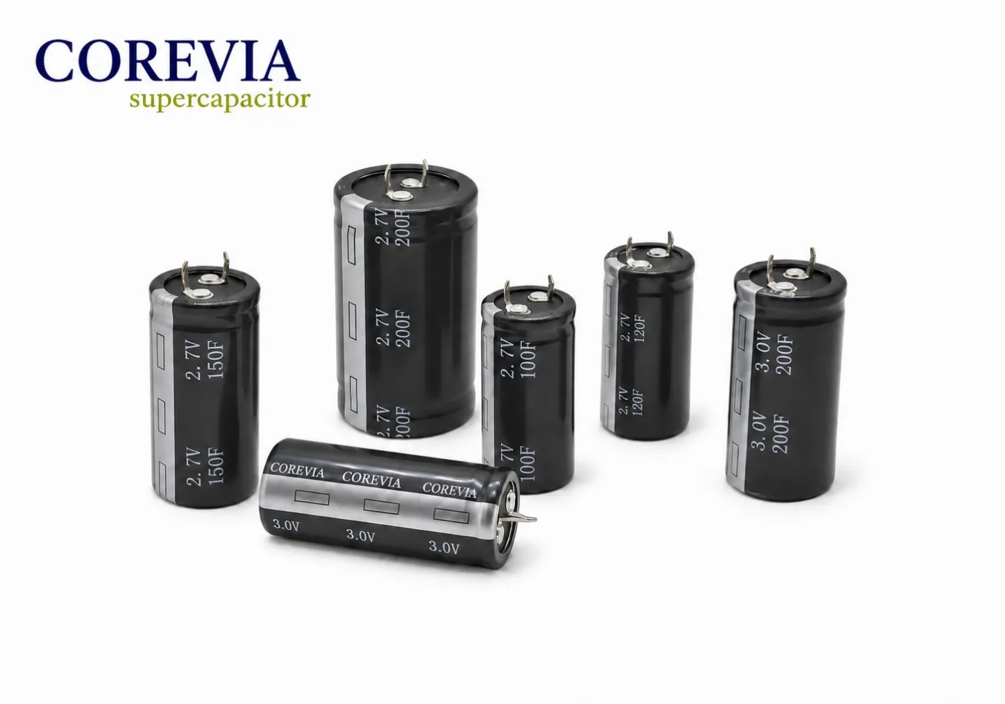
COREVIA lists snap-in terminal supercapacitors in 2.7 V and 3.0 V cell classes, with a published family range of 100 F to 500 F. Those are family-level details, not the usable voltage or backup time of a finished bank. Request the current datasheet for the exact series and part number before setting cell count, charging voltage, balancing method, dimensions or life margin.
When cells are connected in series, bank capacitance falls and individual cell voltages need review. The prior 5 V cell-voltage guide explains that separate design question. For this hold-up calculation, send COREVIA the complete load and voltage window rather than asking for a capacitance value in isolation.
FAQ: practical hold-up checks
Can I calculate backup time from farads alone?
No. The usable voltage span, load profile, ESR, converter behavior and temperature all affect delivered time.
Does a larger cell always solve a short voltage dip?
No. ESR can produce an immediate voltage sag even when stored energy is adequate. Check both transient voltage and total hold-up time.
What should I send for a part recommendation?
Send the controller input limits, measured power profile, target interruption duration, charging source, ambient temperature, available size and expected quantity through the COREVIA technical inquiry page. Ask for a part-specific review and validate the proposed bank in your equipment.