Application Guides
How Should You Insert a COREVIA Snap-In Capacitor Into a PCB?
Before inserting a COREVIA snap-in capacitor, check the exact terminal drawing, PCB holes, polarity and fixture alignment. Use a controlled trial and inspect for stress.
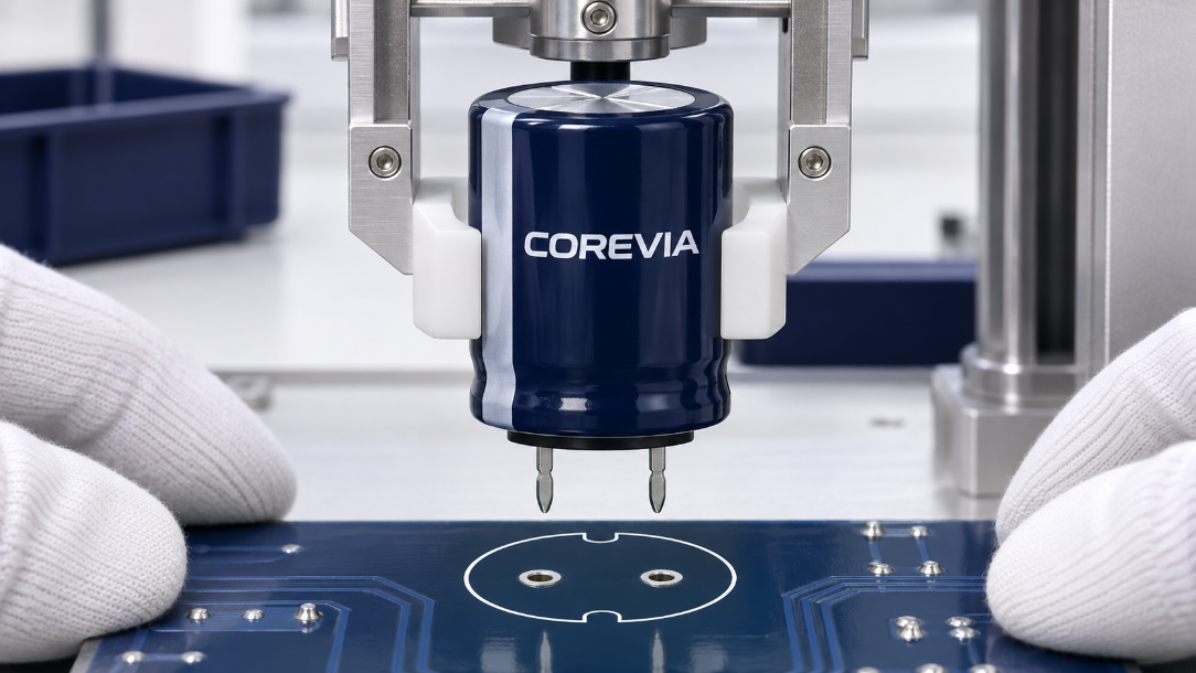
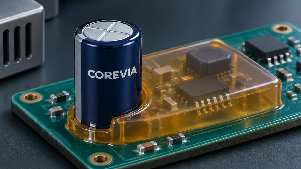
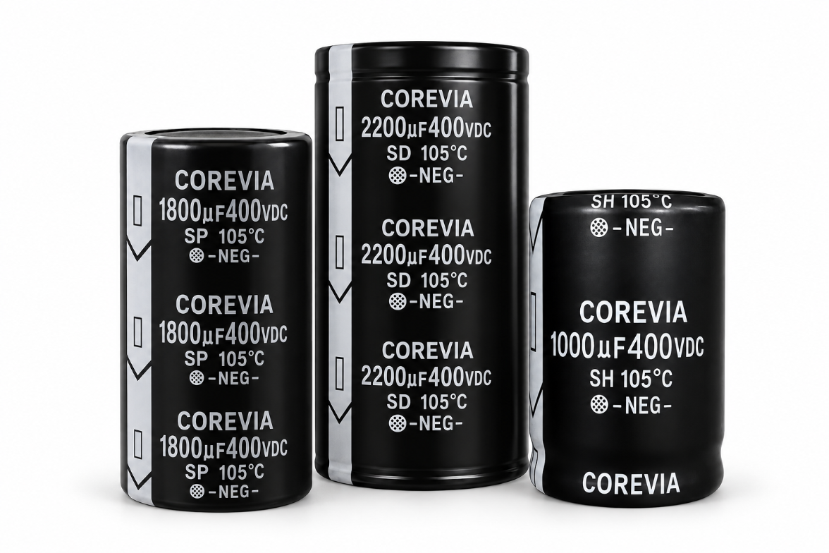
Check the exact COREVIA part drawing and PCB layout before inserting a snap-in capacitor. Confirm terminal spacing, hole geometry and polarity, then align the part squarely and run a controlled trial with the actual board and fixture. Stop if the terminals need to be forced into place or the can rocks, tilts or shows damage. There is no universal insertion-force value that can replace approval for the exact capacitor and assembly.
Which dimensions and orientation must match?
Start with the complete COREVIA part number and its current mechanical drawing. Compare the terminal pattern, polarity indication, body envelope and any support features with the PCB fabrication data. Check the finished hole dimensions and tolerances, not just the nominal CAD footprint. A capacitor that fits an empty drawing may still bind in a fabricated board.
Review the specific COREVIA snap-in capacitor family and request the series drawing if the assembly team does not have it. Do not infer the terminal pattern or polarity from a visually similar part.
How can a trial insertion expose a process problem?
Use a representative production board, approved fixture and the intended insertion sequence. Support the board so it does not flex at the holes. Align all terminals before applying a controlled, even motion. The fixture should contact only areas allowed by the part drawing and should avoid loading the vent, seal and terminals. Record what happens if insertion is not smooth; do not increase machine force simply to make the part seat.
Check | What to record | Reason for review |
|---|---|---|
Part identity and polarity | Full part number, lot and orientation photo | Prevents a visually similar part or reversed layout from being accepted |
Board holes and terminal pattern | Measured finished holes and drawing revision | Reveals mismatch before terminals are stressed |
Fixture contact | Contact points and board support photo | Shows where load enters the can and board |
Post-insertion condition | Can seating, terminal condition, seal and vent photos | Documents whether the trial caused visible damage |
If the trial part does not sit as the exact drawing requires, hold the assembly for engineering review. Do not trim, bend or reshape snap-in terminals as a routine line adjustment without written approval for that part.
What should production inspect after insertion?
Check that the capacitor is aligned, its polarity is correct and the can and sleeve have not been damaged. Inspect the base seal, vent and visible terminal areas. Look for board cracking, lifted pads or abnormal board bow. Compare the installed position with the mechanical drawing and with the clearance to nearby components or metalwork.
Keep the first-article result and fixture settings with the PCB and capacitor revisions. Recheck after a change to board supplier, hole finish, fixture, insertion method or capacitor series. These changes can affect fit even when the electrical design is unchanged.
FAQ: snap-in capacitor insertion
Can operators push harder if the capacitor does not seat?
No generic higher-force setting is safe to assume. Stop, inspect the terminal pattern and finished holes, and review the fixture and exact part drawing.
Can terminals be bent to match a PCB footprint?
Do not make that a standard correction. Request a part-specific engineering decision and correct the drawing or component selection where needed.
Does a visual fit prove the assembly is approved?
No. Visual fit is one check. The approved assembly also needs the correct polarity, drawing match, undamaged part and board, and process evidence.
For an insertion issue, contact COREVIA with the full part number, PCB drawing and revision, finished-hole measurements, fixture photographs and clear images of the affected capacitor.