Application Guides
Can One COREVIA Supercapacitor Cell Connect Directly to a 5 V Rail?
A single COREVIA 2.7 V or 3.0 V supercapacitor cell cannot be connected directly across 5 V. Review cell count, balancing, charge control and the exact series limits.
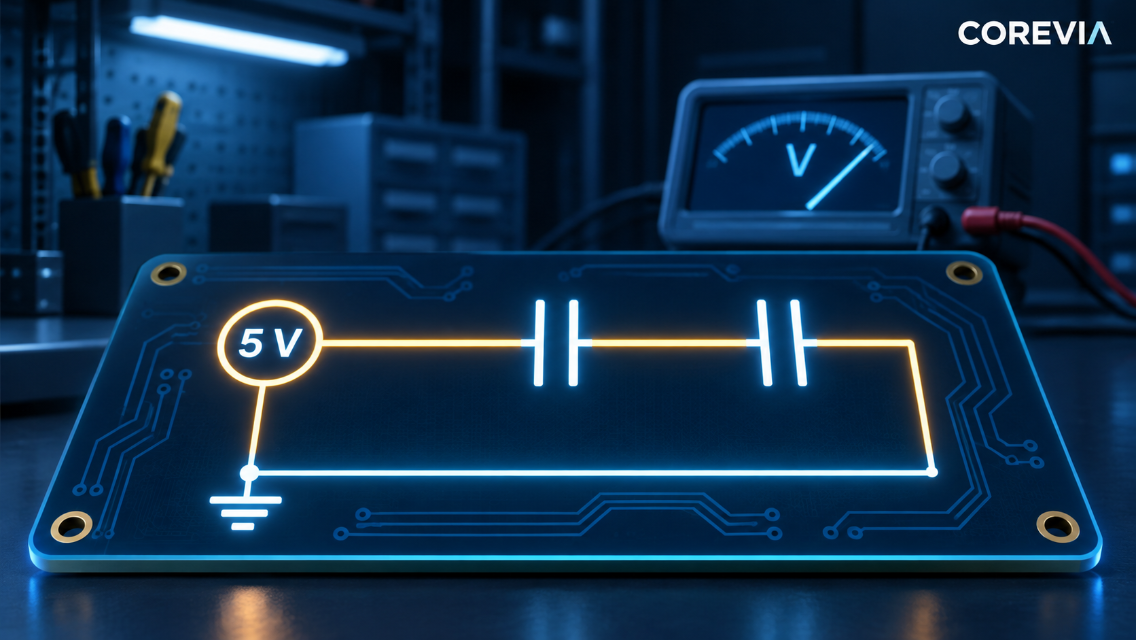
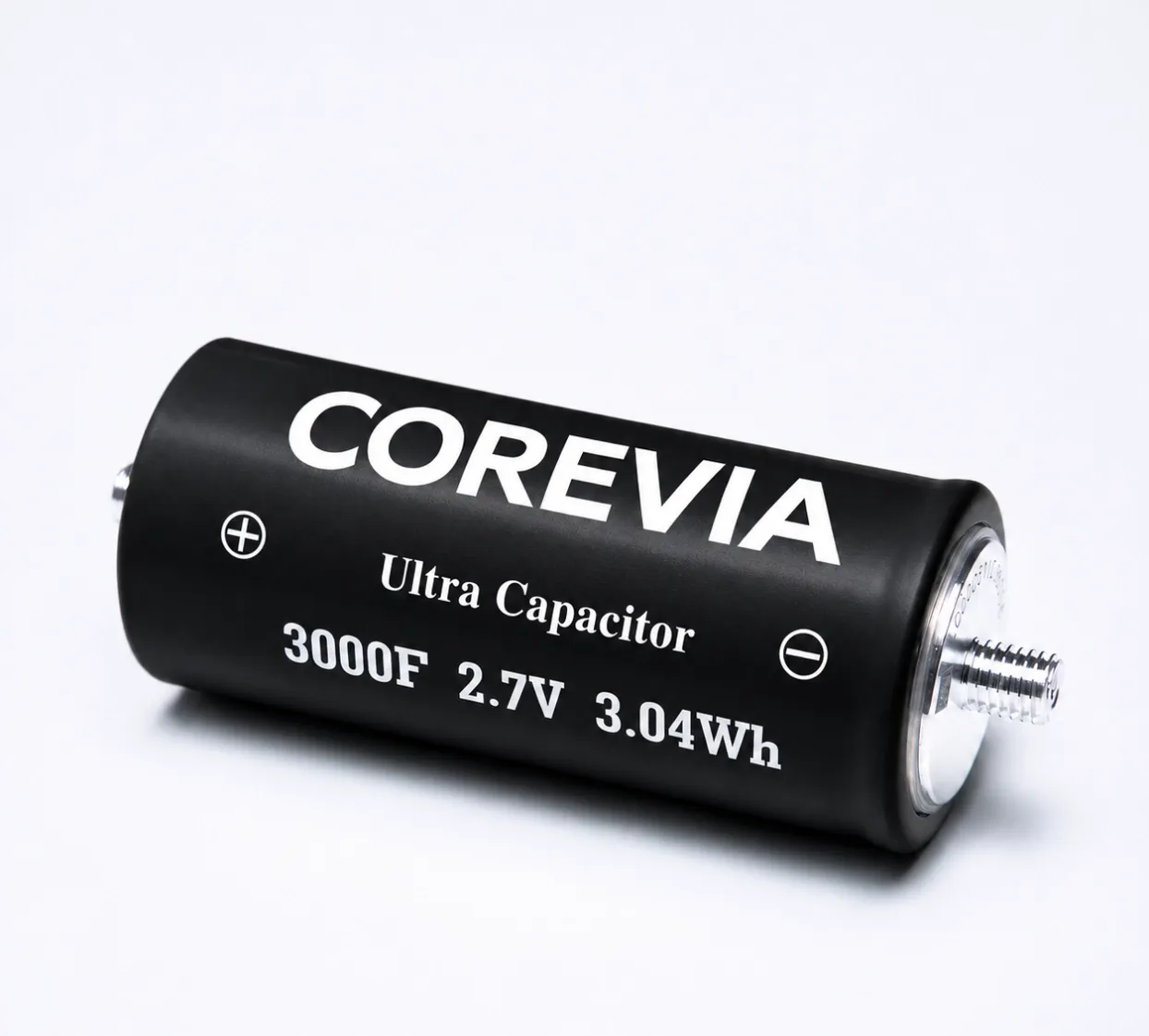
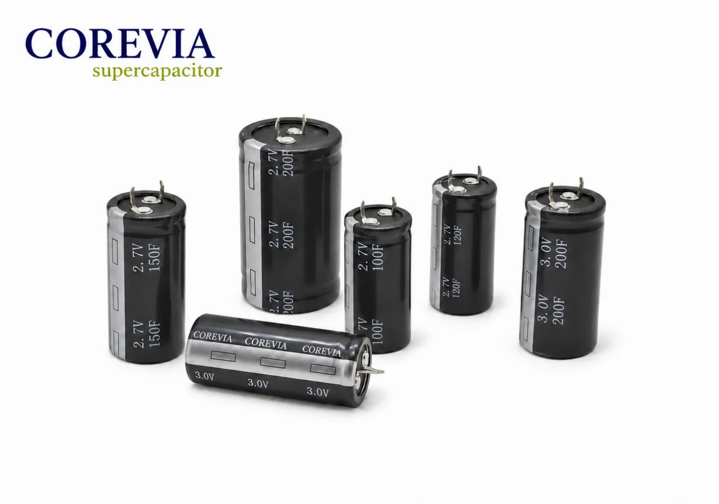
No. A single COREVIA snap-in supercapacitor cell rated 2.7 V or 3.0 V must not be connected directly across a 5 V rail. The rail exceeds the published per-cell voltage class. A series-connected stack may be considered only after the engineer checks the maximum rail voltage, voltage sharing between cells, charge-current control, temperature, available energy and the exact COREVIA series data. Two cells are not automatically an approved 5 V solution.
Why is the voltage on each cell the critical limit?
The COREVIA snap-in supercapacitor family lists 2.7 V and 3.0 V cell classes. These are per-cell ratings. A nominal 5 V supply may have startup overshoot, charger tolerance or other transients, so the highest voltage that can reach the stack matters. The voltage across each cell in a series stack must stay within the limit for the exact part under those conditions.
Do not assume that placing two cells in series guarantees equal voltage on each one. Cell variation, leakage, temperature and aging can cause unequal sharing. The design needs a documented balancing method and a way to verify cell voltages during the relevant operating states.
What should be checked before choosing a series stack?
Specify the full rail profile: normal voltage, maximum sustained voltage, startup and shutdown behavior, transient peaks, charging source and environmental temperature. Then identify the exact COREVIA part number and current datasheet. Check the stack arrangement, balancing circuit, charge-current limit, discharge path, protection and PCB or busbar layout as one system.
Design input | Question to answer | Evidence to keep |
|---|---|---|
Maximum rail voltage | What is the worst sustained and transient voltage? | Measured rail waveform and supply tolerance |
Cell voltage sharing | Can any cell exceed its own rating? | Per-cell measurements across startup, steady state and standby |
Charging behavior | How is inrush or charge current controlled? | Charger schematic and measured current profile |
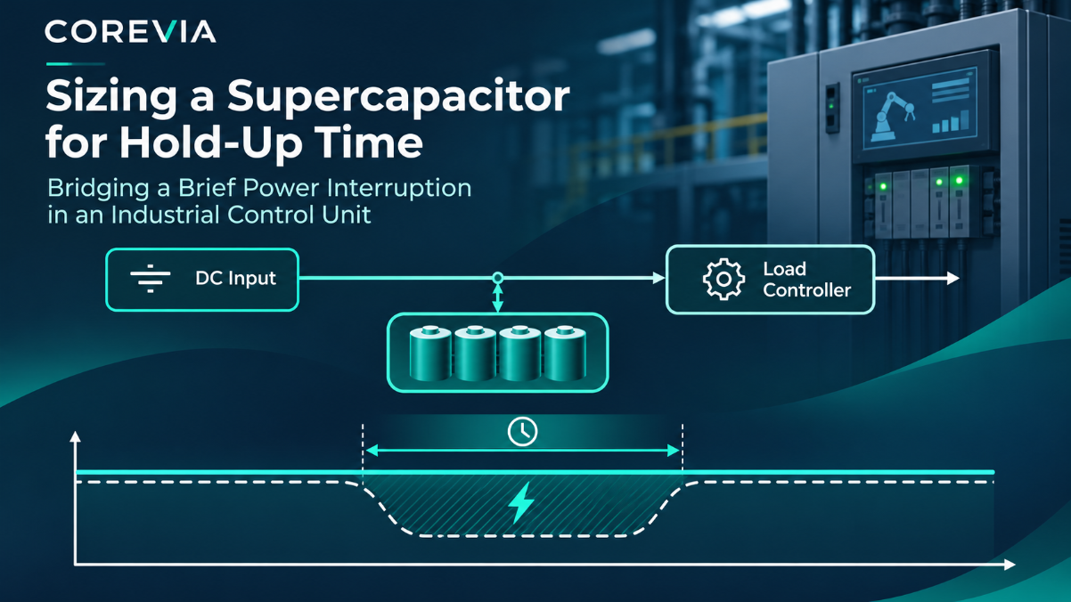
Required backup function | How much usable energy remains above the load cutoff? | Load profile, cutoff voltage and test result |
Part and assembly | Does the exact series meet thermal and mechanical needs? | Datasheet revision and installation drawing |
The table is a design checklist, not a declaration that any particular two-cell combination is qualified. COREVIA must confirm the exact part data used for a selection.
How should a prototype be validated?
Measure each cell voltage with the intended charger, balancing network and load. Include the highest expected input, no-load standby, startup, recovery after a power interruption and the relevant temperature range. Record the charge-current profile and the load's actual hold-up requirement. A stack that passes at room temperature and one operating point still needs review at the design extremes.
Document polarity, installation, protection and discharge handling. Supercapacitors can store substantial energy even when the input is removed; use the site's approved safe-handling procedure during tests.
FAQ: a 5 V rail and supercapacitor cells
Will two 2.7 V cells always be safe on a 5 V rail?
No. Their nominal ratings alone do not establish safe per-cell voltage. Rail peaks, unequal voltage sharing, temperature and charging behavior must be checked for the exact design.
Can a resistor across each cell solve every balancing problem?
No universal resistor value or balancing approach applies. The balancing method must be designed and validated against the actual cells, leakage behavior and operating duty.
Does a larger capacitance rating remove the need for charge control?
No. Capacitance does not replace review of charge current, supply capability, protection or per-cell voltage.
For a COREVIA supercapacitor selection review, send COREVIA the rail waveform, load and backup requirement, temperature range, proposed cell count and charger schematic.