Series-Connected Electrolytic Capacitors: Why Voltage Balancing Matters
Two series capacitors do not automatically share DC-link voltage equally. Check leakage current, balancing resistors, transient behavior and per-capacitor voltage before approval.
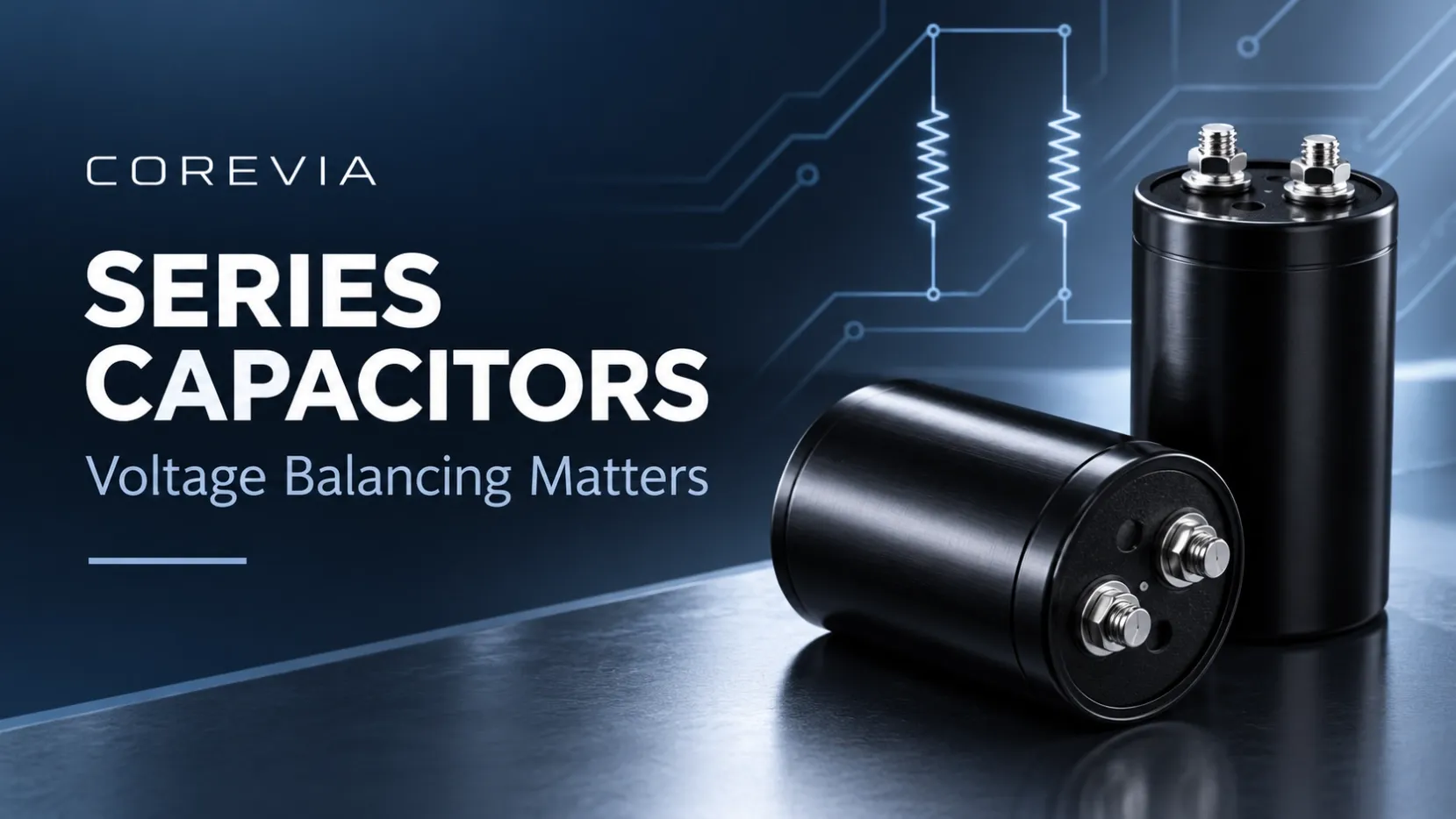
Two aluminum electrolytic capacitors in series do not automatically divide the DC-link voltage equally. A workable design must keep the voltage across each capacitor within its specification during charging, continuous operation and shutdown. Balancing resistors can control steady-state voltage sharing, but their resistance, tolerance, heat dissipation and working-voltage rating need to be checked together.
This guide focuses on conventional liquid-electrolyte aluminum capacitors in UPS, inverter and industrial power-converter DC links. It explains what to review before approving a series-connected bank; it is not a universal resistor recommendation for every capacitor series.
1. Why can two identical capacitors carry different voltages?
A shared part number means the capacitors meet the same specification; it does not mean their capacitance and leakage current are identical. During a fast charging event, capacitance differences influence voltage division. After the bank settles under DC, leakage-current differences become important. Temperature differences between positions can also change operating behavior.
Measuring only the complete bank can therefore miss an overstressed part. For example, a measured 800 V total could consist of 400 V + 400 V, or 470 V + 330 V. The total is unchanged, but the second case would exceed a 450 V rating on one capacitor. These are arithmetic illustrations, not approved operating points.
For equal ideal capacitors, the equivalent series capacitance is C/N. Two 1,000 µF capacitors in series produce 500 µF, not 2,000 µF. This reduction must be included in the DC-link energy and ripple-voltage design.
2. What must be checked when selecting balancing resistors?
A resistor connected across each capacitor provides a deliberate DC current path. Its value must be assessed against the expected leakage-current spread of the selected parts and the permitted voltage imbalance. A copied resistance value from another bank may be unsuitable when capacitance, temperature, leakage limits or circuit topology changes.
| Design item | What to confirm |
|---|---|
| Resistance and tolerance | Calculate worst-case sharing using capacitor leakage variation and resistor tolerances, then verify by measurement. |
| Power dissipation | Use P = V²/R for the actual resistor voltage; apply the resistor manufacturer's thermal derating. |
| Working voltage | Check continuous and transient voltage limits separately from the wattage rating. |
| Physical placement | Keep resistor heat from creating an unnecessarily hot capacitor position; check clearances and cooling. |
| Failure behavior | Review what happens if a resistor opens or a capacitor shorts; balancing is not a substitute for fault protection. |
A calculation example: resistor losses are not negligible
Assume, only for illustration, that a resistor sees 400 V and has a resistance of 100 kΩ. The resistor current is 400/100,000 = 4 mA, and dissipation is 400²/100,000 = 1.6 W. Two such resistors dissipate 3.2 W in total. This calculation shows the heat budget; it does not establish that 100 kΩ or a nominal 2 W resistor is suitable. Actual selection also depends on leakage spread, voltage rating, ambient temperature, mounting and derating.
For a COREVIA design review, use the exact capacitor series specification and the intended operating conditions to assess leakage-current variation and voltage margin. General calculation examples do not replace qualification of the finished capacitor bank.
3. How should the complete bank be qualified?
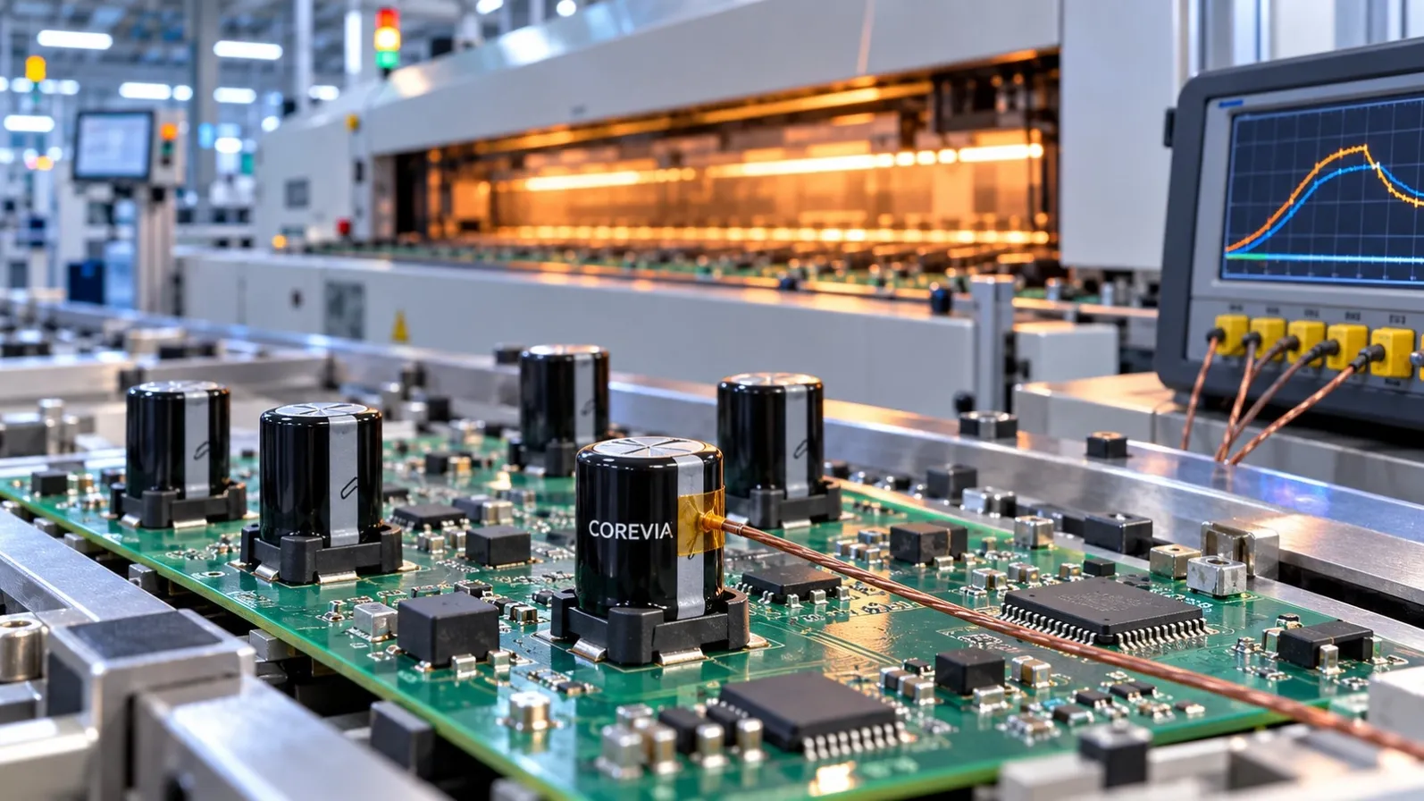
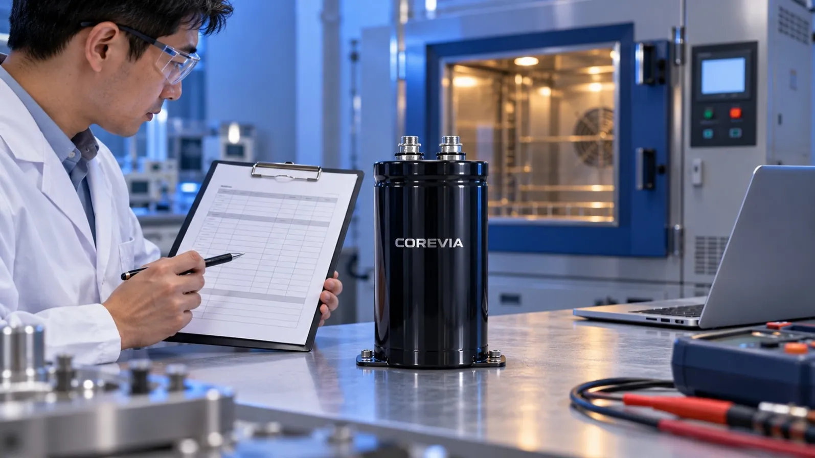
Record the individual capacitor voltages as well as the total bus voltage. Evaluate the relevant conditions: startup and pre-charge, normal load, maximum bus voltage, thermal stabilization, load changes and shutdown. A resistor network that gives acceptable steady-state sharing may not correct a fast transient or an actively loaded midpoint.
- Confirm polarity, terminal layout, creepage, clearance and the exact series/parallel arrangement.
- Use the intended capacitor series and case size, with its stated capacitance, ripple-current and temperature limits.
- Check both positions for local heating, including nearby balancing resistors and other hot components.
- Use appropriately rated isolated or differential measurement equipment and a qualified high-voltage test procedure.
- Document acceptance limits for every capacitor voltage before testing, rather than judging only the total bus reading.
If the circuit draws current from the midpoint, include that load explicitly in the balancing analysis. Do not assume that a divider designed only around leakage current will support it. Likewise, a discharge function requires its own assessment: balancing resistors do not by themselves prove a safe discharge time or a de-energized bus.
4. What information should you send for a COREVIA review?
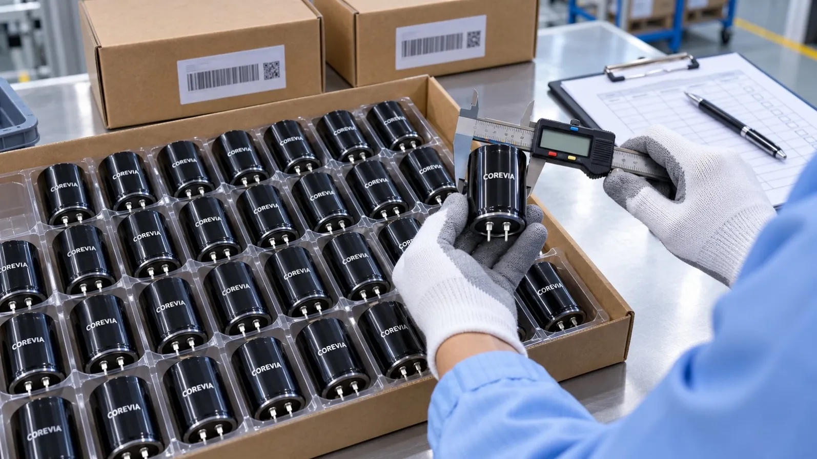
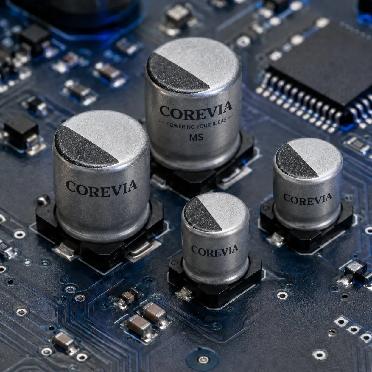
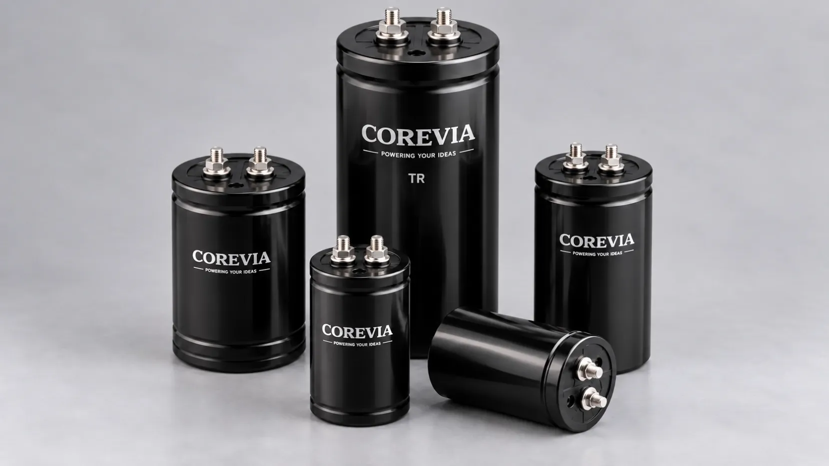
COREVIA offers screw terminal aluminum electrolytic capacitor families and snap-in aluminum electrolytic capacitor families. Terminal format alone does not qualify a part for a particular series-connected bank. Start with the exact series datasheet and the circuit conditions.
For a focused review, provide the total bus voltage including expected peaks, number of capacitors in series and parallel, target equivalent capacitance, part number or existing datasheet, ripple current and frequency, temperature at each position, balancing circuit, midpoint loads and available mounting space. Include startup/shutdown waveforms and measured individual capacitor voltages if available.
FAQ
Can two 450 V capacitors automatically be treated as a 900 V bank?
No. Adding ratings does not establish acceptable individual voltage sharing, transient margin or operating life. Validate the maximum voltage on each part.
Does using the same production lot remove the need for review?
No. Parts from one lot still have permitted variation, and their installed temperatures can differ. Review the balancing method and verify the finished equipment.
Can an old balancing resistor value be reused after changing capacitor size?
Recheck it. A different capacitance or series can change leakage behavior, while the existing resistor's voltage and thermal limits still apply.
Next step: Send COREVIA your bank schematic and operating conditions to discuss capacitor selection. Confirm the proposed part and balancing design before production approval.