Sep 15, 2026Reliability Engineering
Why Did This Screw-Terminal Capacitor’s Top Cover Blow Open?
A field-based analysis of what a lifted terminal cover, scorched rim and deformed can reveal about internal pressure, electrical stress and overheating.
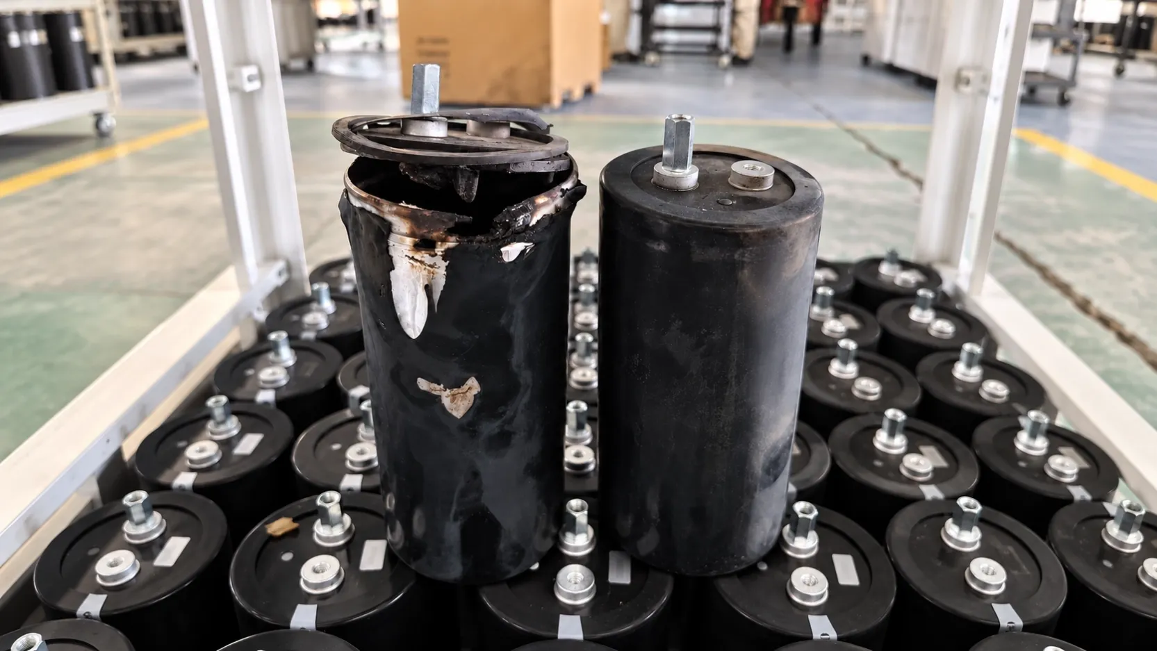
The lifted cover catches your attention. The burn marks tell the more important story.
This screw-terminal aluminum electrolytic capacitor did not simply wear out. The raised terminal deck, scorched sealing area, melted sleeve and deformed can point to a rapid internal-pressure event accompanied by severe local heating.
The top cover is therefore not the root cause. It is the final part displaced after pressure built up inside the capacitor.
What the visible damage tells us
The terminal deck has been forced away from the aluminum can. This means the pressure inside the capacitor exceeded what the sealing and pressure-relief structure could manage at that moment.
The burned area around the rim is another important clue. It is consistent with hot gas and electrolyte escaping from the opening. Local electrical arcing near a terminal or connection point is also possible, so the terminal surfaces and original busbar connections should be inspected before reaching a conclusion.
The severe deformation suggests a relatively fast, high-energy event. Normal electrolyte loss and long-term aging may have contributed, but slow aging alone does not fully explain this appearance.
The probable failure sequence
- An abnormal electrical or thermal condition increased current and internal heating.
- The electrolyte began to vaporize or generate gas faster than normal.
- Internal pressure rose faster than the relief system could discharge it.
- The terminal deck was pushed upward, releasing hot gas and electrolyte around the rim.
Root causes that should be investigated
Overvoltage or uneven voltage sharing
Voltage above the capacitor rating can sharply increase leakage current, damage the dielectric oxide layer and accelerate gas generation.
If capacitors are connected in series, measuring only the total DC-bus voltage is not enough. Each capacitor must be measured individually. Differences in leakage current or a damaged balancing resistor can place excessive voltage on one unit even while the total bus voltage appears normal.
Reverse-polarity events
Aluminum electrolytic capacitors are polarized components. Reverse voltage can rapidly damage the dielectric layer, produce heat and raise internal pressure. Polarity should be checked during startup, shutdown, regenerative operation and abnormal switching conditions—not only during steady operation.
Excessive ripple current
Ripple current produces heat inside the capacitor. If the actual current or harmonic spectrum exceeds the capacitor’s capability, its core temperature rises. An aged capacitor with higher ESR will generate even more heat under the same load, creating a cycle of rising temperature and accelerating deterioration.
Internal insulation breakdown
A localized dielectric defect may develop into an internal short circuit. The resulting current can create intense heat in a small area and raise pressure very quickly. The severity of the damage makes this an important possibility to verify through teardown and electrical testing.
Poor terminal contact or external arcing
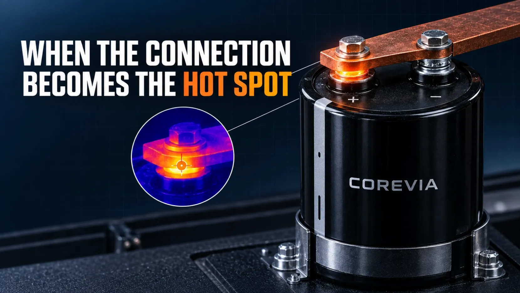
A loose terminal, incorrect tightening torque, an uneven busbar surface or oxidation can create high contact resistance and local heating. In severe cases, arcing can occur near the terminal assembly.
Look for pitting, melted metal and heat discoloration on the original terminal hardware. These details help distinguish heat produced inside the capacitor from heat originating at the external connection.
Restricted pressure-relief operation
The pressure-relief area needs sufficient free space. Nearby busbars, covers, wiring and mechanical structures must not restrict its movement or block the discharge path. A relief device reduces risk, but it cannot compensate for unlimited fault energy or an obstructed outlet.
Why the neighboring capacitor matters
The adjacent capacitor appears much less damaged. If both units operated under the same general system conditions, this difference is useful evidence. One unit may have experienced higher voltage, poorer cooling, a weaker connection or more advanced internal degradation.
This does not prove the problem was limited to one capacitor. Every remaining unit in the bank should still be checked before the equipment returns to service.
Recommended investigation
Before inspection, isolate the equipment and discharge every capacitor using the approved safety procedure. Then check:
- Operating voltage across each individual capacitor
- Transient and surge-voltage records
- Polarity during every operating state
- Balancing-resistor values and connections
- Ripple current and harmonic content under real load
- Capacitor case and terminal temperatures
- Terminal torque and contact condition
- Clearance around the pressure-relief area
- Capacitance, ESR and leakage current of the remaining units
- Cooling airflow, ambient temperature and operating history
Final takeaway
Replacing the damaged capacitor may restart the equipment. It does not explain why this unit absorbed more electrical or thermal stress than the others.
The cover shows where the pressure escaped. A reliable failure analysis must still find where the pressure started.
COREVIA
Aluminum Electrolytic Capacitor Solutions
Website: www.coreviacap.com
Email: sales@coreviacap.com