Electrolytic Capacitor Tolerance: Will Your Power Supply Meet Hold-Up Time?
Calculate power-supply hold-up time with minimum capacitance, starting bus voltage and converter cutoff. See how tolerance changes the result before approving a capacitor.
Use the minimum capacitance allowed by the exact part specification—not only the value printed on the sleeve—to check power-supply hold-up time. Also use the lowest bus voltage available when input power disappears and the voltage at which the downstream converter stops regulating. A nominal-capacitance calculation that just meets the target leaves no allowance for negative capacitance tolerance.
This guide addresses one design question: can a capacitor that meets its own specification still leave the power supply short of the required ride-through time? Yes, if the system was sized using nominal values alone.
1. Define the energy the power supply can actually use
A capacitor does not deliver all its stored energy before the converter shuts down. For an ideal capacitor, usable energy between two bus voltages is:
E = ½ × C × (Vstart² − Vstop²)
C is capacitance in farads. Vstart is bus voltage at the beginning of the interruption; Vstop is the lowest usable bus voltage. For an approximately constant power drawn from the capacitor, the energy balance gives t = C × (Vstart² − Vstop²) / (2 × Pbus), where time is in seconds and Pbus is in watts.
Keep the power reference consistent. If the requirement is expressed as output power, allow for converter losses when determining power drawn from the bus. Use the actual load behavior where power changes during the interruption. The difference of squared voltages is not the square of the voltage difference.
2. Calculate the lower-tolerance case before choosing nominal capacitance
The following values are an illustrative calculation, not COREVIA product ratings or a tested power-supply result. Assume a single-capacitor equivalent of 1,000 µF, a hypothetical −20% lower capacitance tolerance, a bus falling from 400 V to a 300 V cutoff, and a constant 1,000 W drawn from the bus. Ignore ESR and other losses for this first calculation.
| Calculation case | Capacitance | Usable energy | Ideal hold-up time |
|---|---|---|---|
| Nominal value | 1,000 µF | 35 J | 35 ms |
| Hypothetical lower tolerance limit | 800 µF | 28 J | 28 ms |
A 30 ms requirement appears to pass at nominal capacitance but fails at the assumed lower limit. Rearranging the same energy balance gives a minimum effective capacitance of about 857 µF for 30 ms. If the agreed lower tolerance were −20%, the nominal value would need to exceed about 1,071 µF even before other allowances.
This result does not establish a recommended part number. A lower starting bus voltage, conversion losses or a higher cutoff can change the required capacitance. A bank with series-connected capacitors also needs the correct equivalent capacitance and a separate voltage-sharing review.
3. Turn the calculation into a COREVIA part review
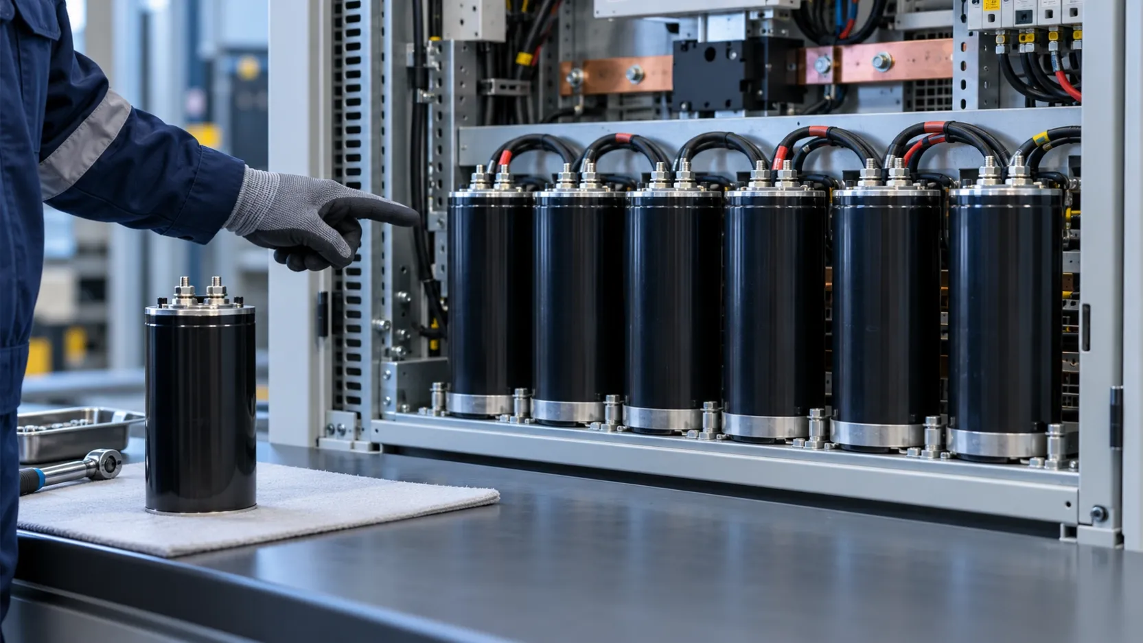
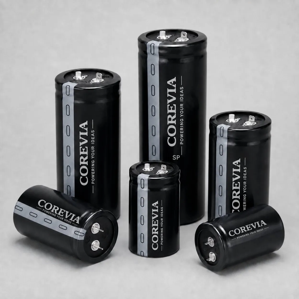
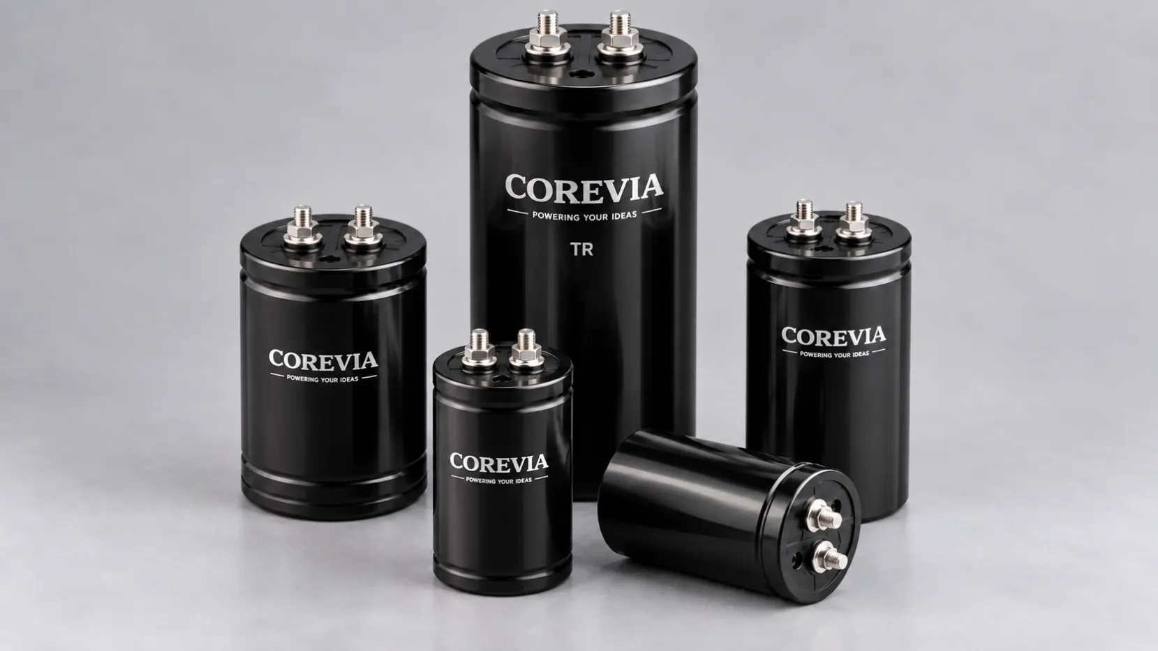
The COREVIA snap-in capacitor portfolio includes SP and SH standard series alongside long-endurance options such as SF, SU, SD and SZ. A family range is a starting point for selection; it does not confirm that every voltage, capacitance and case-size combination is available. Request the exact part specification and its capacitance tolerance before approving the design.
| Review item | What to establish |
|---|---|
| Initial capacitance | Lower tolerance limit and specified measurement conditions |
| Bus operating window | Minimum starting voltage and actual converter cutoff |
| Load demand | Bus power during the interruption, including downstream losses |
| Operating margin | Temperature effects, ESR, ripple-current heating and expected capacitance change over service |
| Assembly qualification | Measured hold-up time at the defined load and operating limits |
Keep initial production tolerance separate from capacitance change during service. Do not subtract an endurance-test limit from nominal capacitance and call the result a guaranteed field-life value. Agree the intended service conditions and validation margin for the exact application.
4. Frequently asked questions
Is −20% the tolerance for every COREVIA capacitor?
No. It is an assumption in this worked example. Use the tolerance and test conditions stated for the exact proposed part.
Can I guarantee hold-up time by measuring one sample?
A sample result confirms that sample and test setup. Production approval also needs the specified lower capacitance limit and the defined system operating limits.
Should I simply add a larger capacitor?
Recheck inrush and pre-charge behavior, physical fit, ripple-current capability and the converter design before changing capacitance. More nominal capacitance alone is not a complete qualification.
What should I send to COREVIA?
Send the required hold-up time, bus-voltage window, load-power profile, target capacitance, temperature, ripple current, case dimensions and quantity. Contact COREVIA for a capacitor specification review and identify which values are fixed requirements and which remain design assumptions.