Reliability Engineering
How Do You Prevent Reverse Voltage Across a COREVIA Capacitor at Power-Off?
A positive DC bus in normal operation does not rule out reverse voltage at shutdown. Learn what to measure across a COREVIA electrolytic capacitor and how to review the circuit.
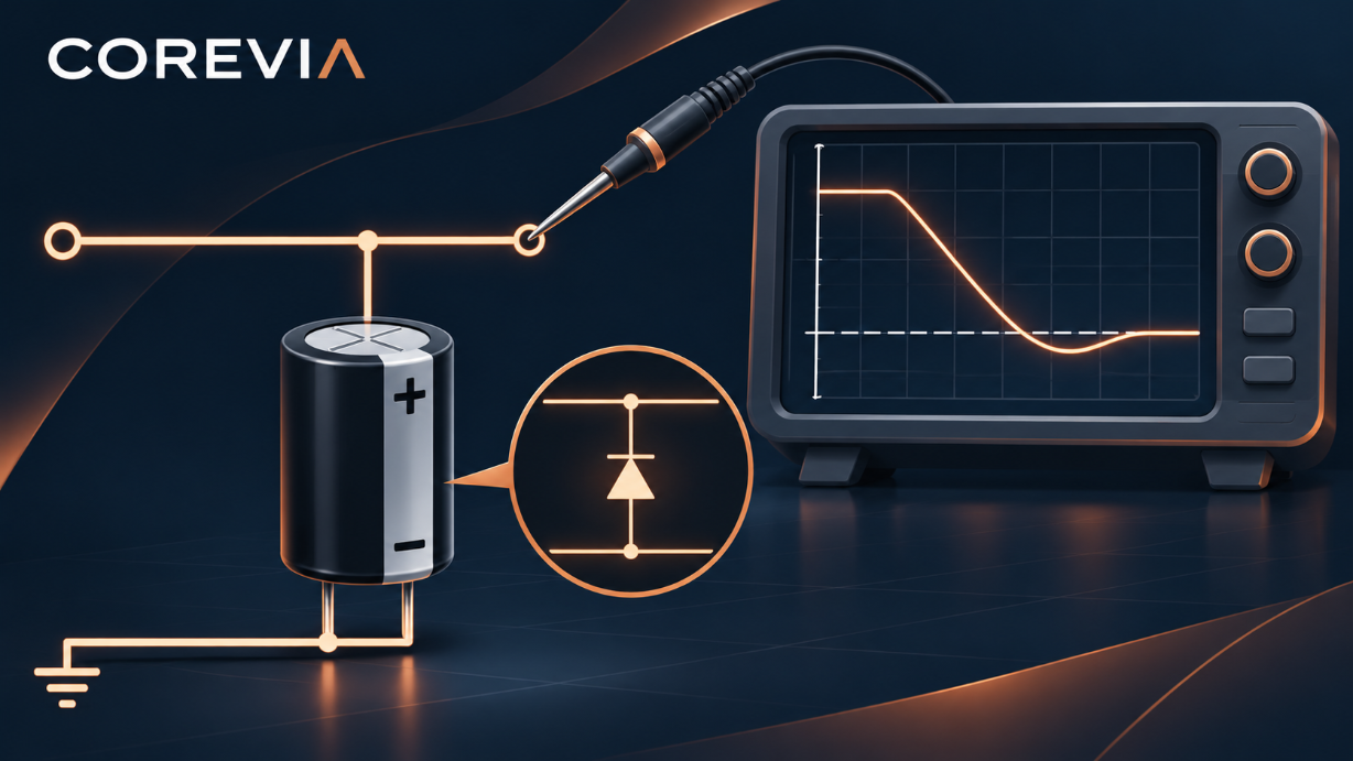
Prevent reverse voltage at power-off by measuring the voltage directly across the capacitor during every shutdown path and changing the circuit if its polarity reverses. A polarized COREVIA aluminum electrolytic capacitor should not be treated as a component that can absorb a negative excursion just because normal running voltage is positive. The relevant question is what the two capacitor terminals experience while supplies and loads decay at different rates.
How can a negative terminal voltage appear during shutdown?
A main DC rail may fall faster than an auxiliary rail, a connected load may return energy, or a second capacitor bank may retain charge after the first loses it. In each case, a node that was positive in steady operation can momentarily move below the capacitor's return node. The magnitude and duration depend on the actual circuit, load and switching sequence. This is different from installing the component with reversed leads before power-up.
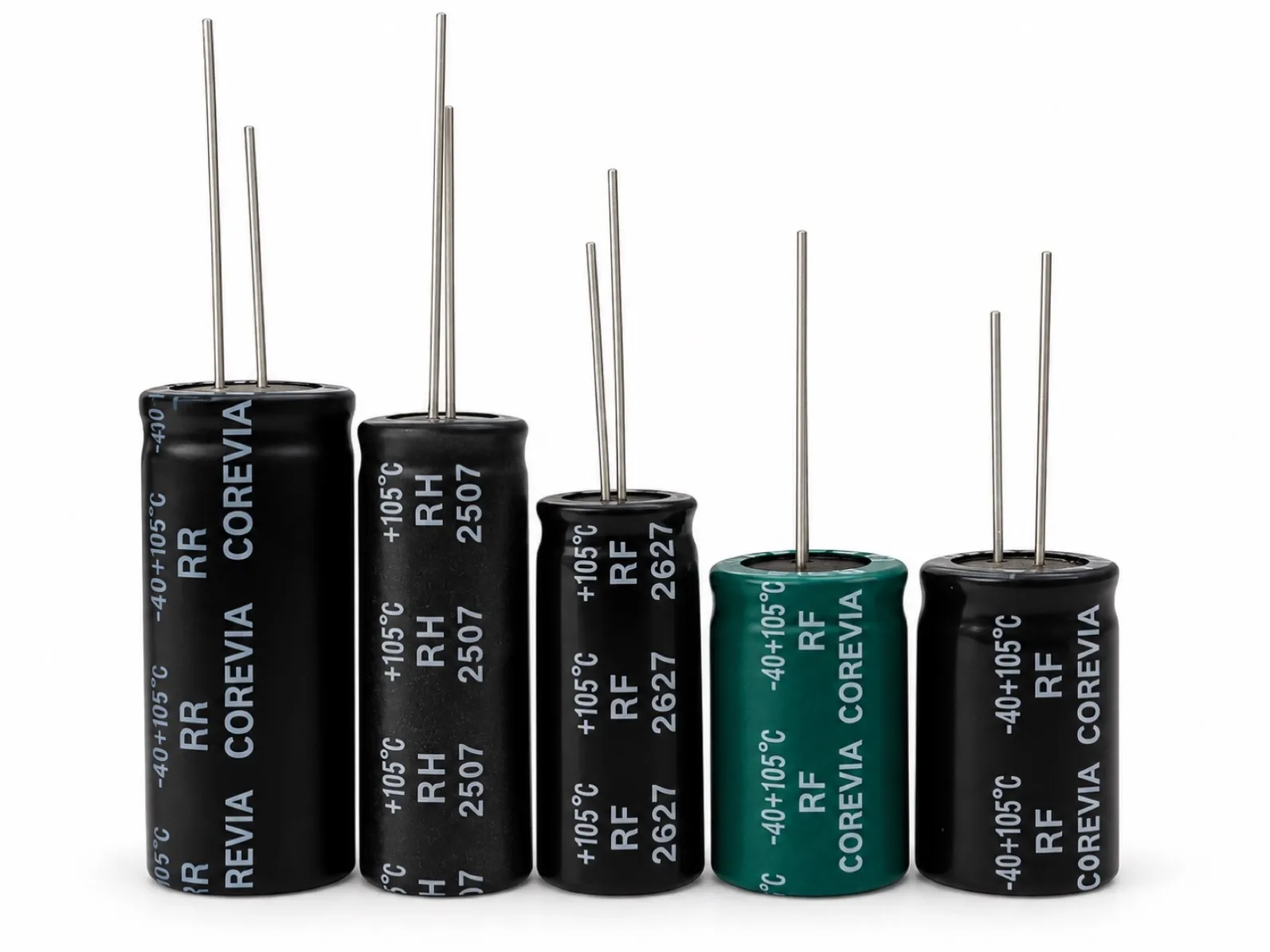
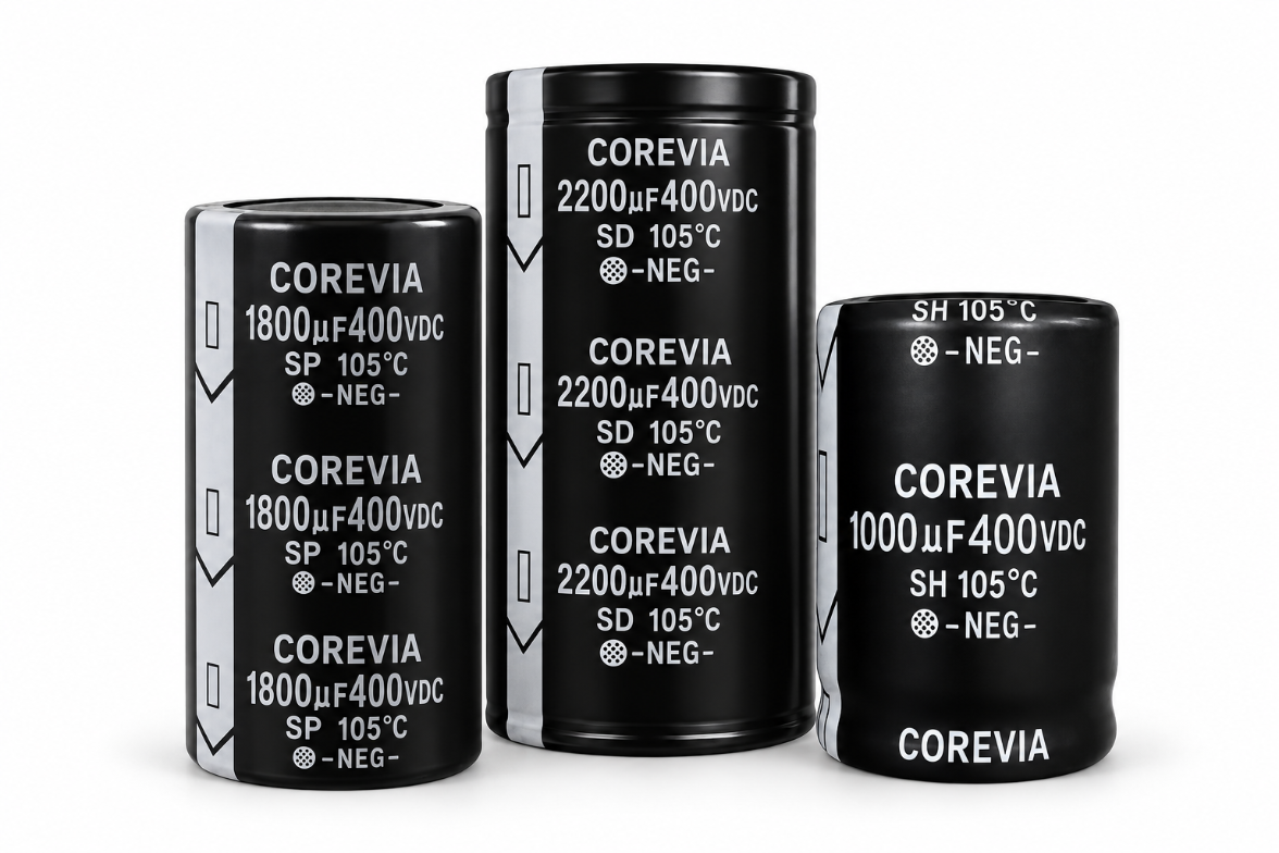
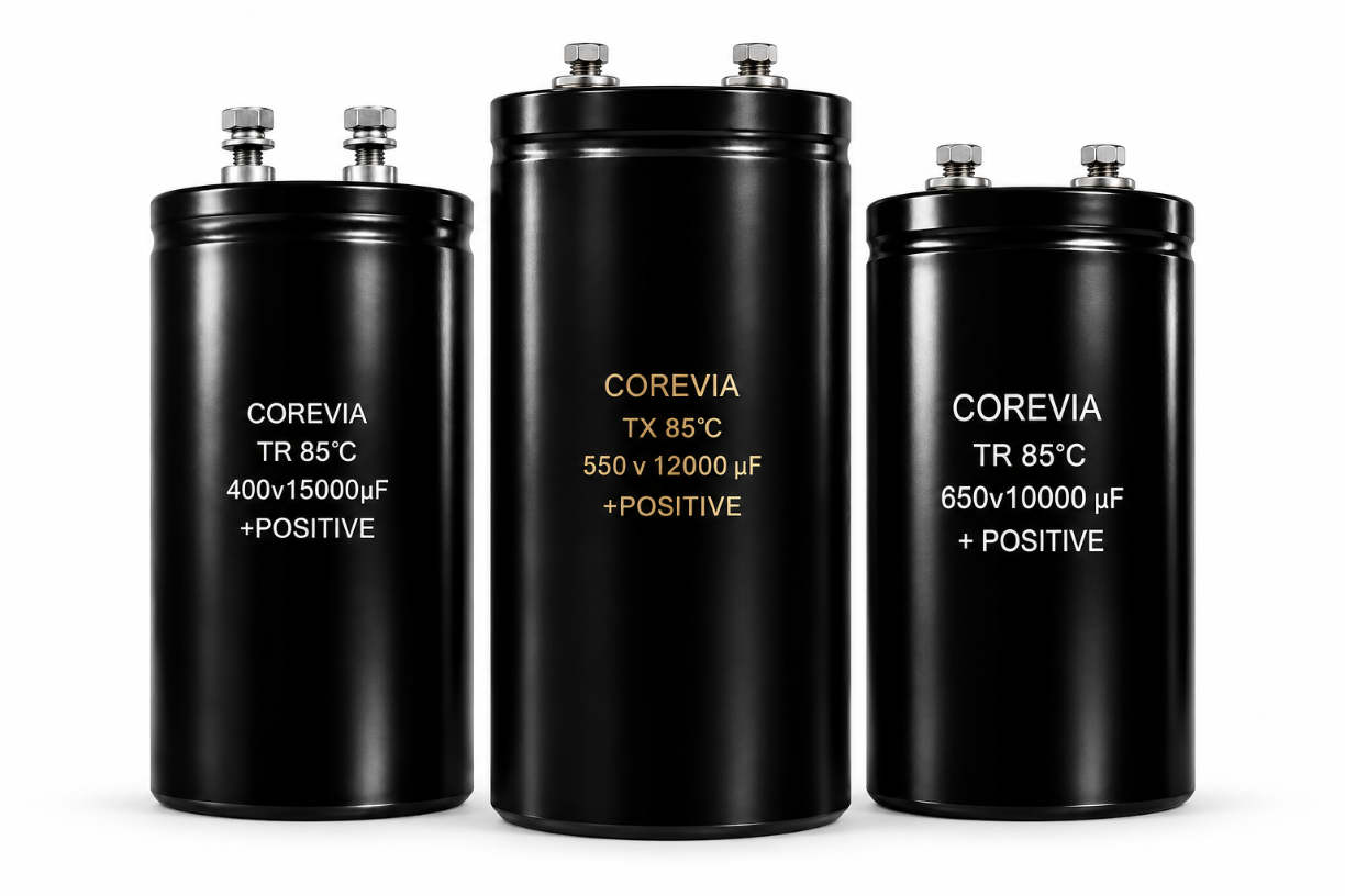
For COREVIA snap-in or screw-terminal aluminum electrolytic capacitors in a power converter, review the full path between the capacitor terminals, not just the labeled bus voltage. COREVIA's product portfolio identifies the terminal families; the selected series and exact part drawing still determine the applicable electrical and mechanical limits.
What should an engineer capture on the bench?
Use a measurement setup rated for the circuit voltage and follow the equipment's isolation and discharge procedure. Capture the differential voltage across the capacitor terminals during normal switch-off, emergency stop, input loss, failed start and any regenerative load transition that the equipment can produce. A rail-to-chassis trace alone may miss the actual voltage across the part.
Record | Decision it supports |
|---|---|
Exact COREVIA series and part number | Connects the finding to the correct datasheet and terminal arrangement. |
Voltage at the capacitor terminals, including sign | Shows whether a reverse excursion occurs. |
Worst-case shutdown mode and load state | Identifies the sequence that creates the excursion. |
Peak negative value and duration | Provides evidence for a part-specific technical review. |
Temperature and repeated-cycle behavior | Tests whether the event changes across operating conditions. |
Compare traces at the capacitor terminals for each realistic operating state. Use the exact series documentation and a COREVIA engineering review for acceptance; do not substitute a generic reverse-voltage allowance.
How should the circuit be corrected?
First identify the path that drives the capacitor positive terminal below its negative terminal. Depending on the equipment, the remedy may involve the shutdown sequence, discharge path, load isolation or a protection component. Each option changes current paths and must be checked for startup behavior, fault energy, thermal stress and service safety. A schematic symbol or a single bench capture is not proof of a validated protection design.
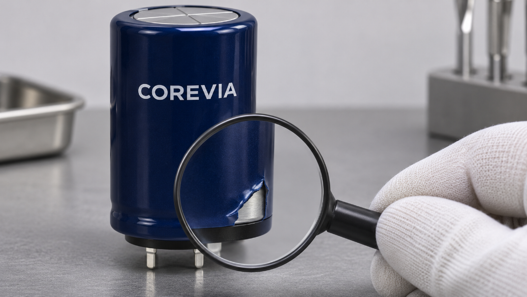
If an unexpected reverse excursion has already occurred, hold the affected assembly and record the waveform and part identification for disposition. Do not assume a later normal capacitance reading proves the capacitor was unharmed.
FAQ: reverse voltage at power-off
Is a positive DC bus during operation enough to prove polarity is safe?
No. Check voltage across the part during shutdown and fault sequences as well as normal operation.
Can a diode always fix the problem?
No. A protection path must be assessed against current, energy, startup and fault behavior in the actual circuit.
What should I send COREVIA for review?
Send the exact capacitor part number, schematic section, capacitor-terminal waveform, shutdown sequence, temperature and load conditions via the COREVIA technical inquiry page. Request a part-specific review before approving production.