Reliability Engineering
Can You Install a COREVIA Snap-In Capacitor With a Torn Sleeve?
A torn sleeve on a COREVIA snap-in capacitor needs a documented hold and inspection. Check the can, vent, seal, marking and installed clearance before disposition.
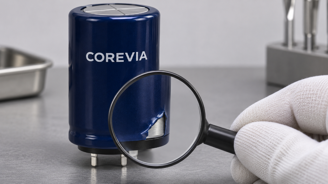
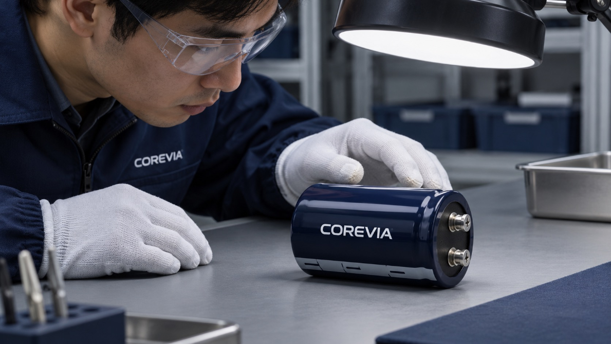
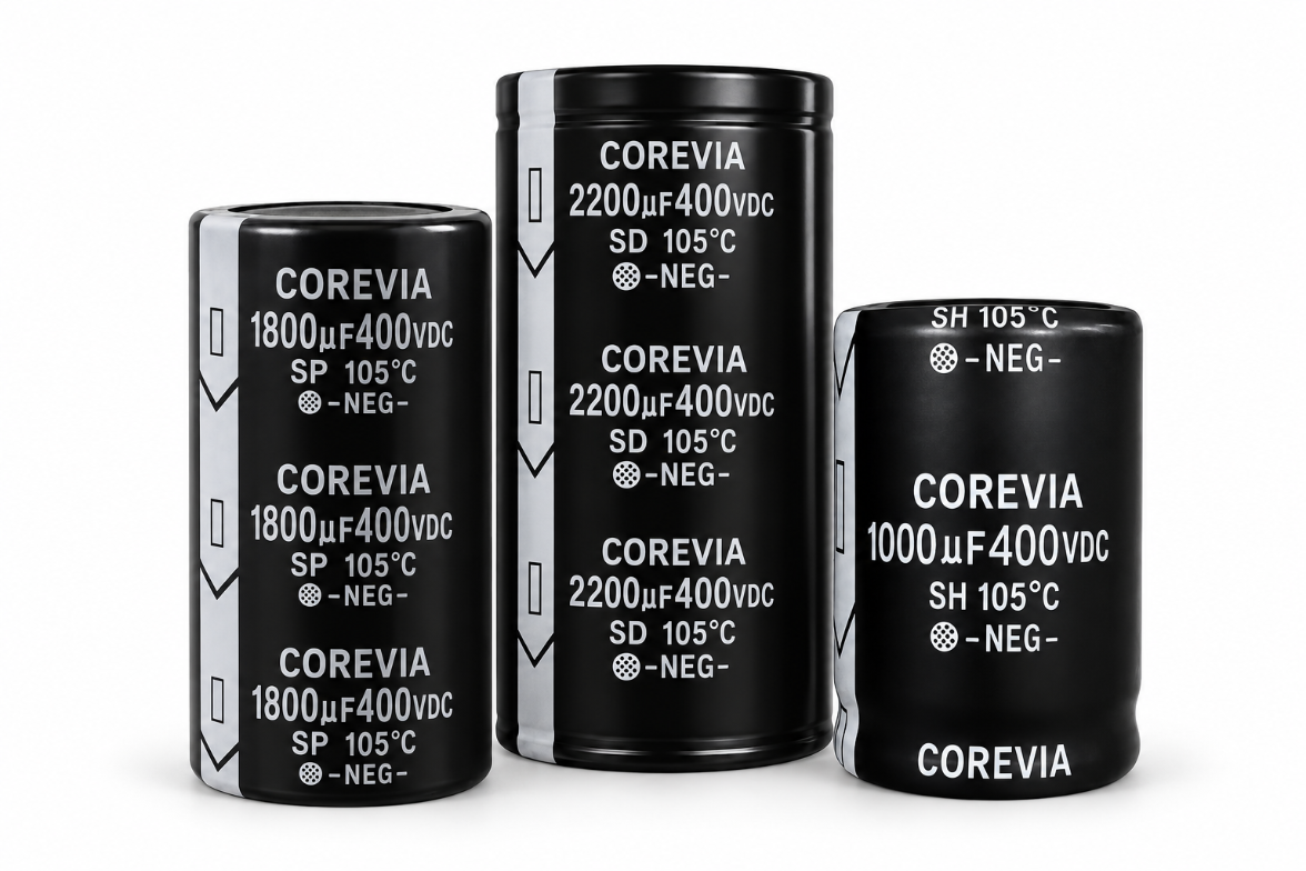
Do not release a COREVIA snap-in capacitor with a torn outer sleeve straight into production. Segregate the part, photograph the defect and check whether only the sleeve is affected or the metal can, vent, seal, marking or terminals are also damaged. The sleeve's appearance alone cannot prove that the capacitor is electrically safe, and it should not be treated as a guaranteed insulation barrier without the exact series documentation.
What does the tear reveal, and what remains unknown?
A sleeve can be scratched by packaging, handling, a clamp or assembly tools. A superficial mark, a split that exposes metal, and a damaged can are different findings. Inspect the entire circumference, top vent, base seal and terminal area under good light. Record whether the part number, polarity and lot information remain readable. Do not bend terminals or peel back more sleeve simply to improve a photograph.
For COREVIA's snap-in capacitor families, the correct disposition depends on the exact part and installation. A visible metal patch can create a contact concern where a clamp, chassis or adjacent conductor is close. It does not, by itself, establish whether the internal element has been harmed. Keep those questions separate.
How should production classify and document the finding?
Quarantine the affected unit and identify the shipment, part number, lot, quantity and assembly stage. Compare it with an undamaged unit from the same shipment. Check the applicable drawing and any agreed incoming or assembly inspection criteria; do not invent a universal permitted tear size. If the can is dented, the vent is disturbed, electrolyte is visible, or the seal or terminals are damaged, escalate the finding for part-specific review.
Observation | Immediate action | Evidence for review |
|---|---|---|
Surface scuff with no visible split | Record and compare with agreed visual criteria | Photo, position and part identity |
Sleeve split exposing metal | Segregate; assess clearance and mounting contact | Close-up and installed-layout drawing |
Unreadable polarity or part marking | Hold; do not infer orientation from appearance | Photos and label or packing trace |
Can, vent, seal or terminal damage | Hold for COREVIA engineering disposition | All-side photos, quantity and handling history |
Keep a written disposition tied to the individual part or lot. If similar tears appear on multiple units, investigate the packaging, clamping and insertion process before releasing the rest of the batch.
What should be checked before any approved installation?
If COREVIA and the customer's quality team approve a disposition, check the installed clearance between the exposed can area and conductive parts under normal assembly tolerances. Review whether a clamp or adhesive contacts the sleeve and could enlarge the tear. Confirm the part's electrical and thermal specifications separately; a routine electrical reading cannot prove that damaged external insulation or a vent obstruction is acceptable.
For a production-line finding, document where the tear first appeared: at unpacking, insertion, soldering, handling or final assembly. That timeline helps prevent recurrence. Use the exact COREVIA series drawing and approved assembly criteria for the final release decision.
FAQ: torn capacitor sleeves
Can a small sleeve tear be covered with tape?
Do not substitute an unqualified tape repair for an engineering disposition. Adhesive compatibility, heat, fit and electrical clearance all need review for the exact assembly.
Does a torn sleeve mean the capacitor is internally defective?
Not necessarily. A sleeve tear and internal electrical damage are different findings. Inspect the can, vent, seal and terminals, then apply the agreed part-specific inspection criteria.
Can the metal can touch a mounting clamp?
That depends on the exact capacitor construction and approved mounting design. Do not assume the sleeve or an exposed can is a qualified isolation interface; verify the drawing and installation requirements.
For a part-specific decision, send COREVIA the full part number, lot details, clear photographs, affected quantity and a drawing of nearby metalwork.