Do Parallel DC-Link Capacitors Need Individual Fuses?
Individual fuses are not a universal rule for parallel DC-link capacitors. Review stored energy, fault paths and protective-device coordination for the actual bank design.
Not every parallel DC-link capacitor bank requires one fuse per capacitor, and a fuse should not be added by rule of thumb. The right protection scheme depends on the bank topology, available fault energy, busbar or PCB layout, upstream protection and the equipment's safety requirements. A capacitor pressure-relief vent responds to internal pressure; it is not a substitute for an electrical protective device. Have the equipment engineer analyze credible faults and coordinate any selected fuse with the actual circuit before production release.
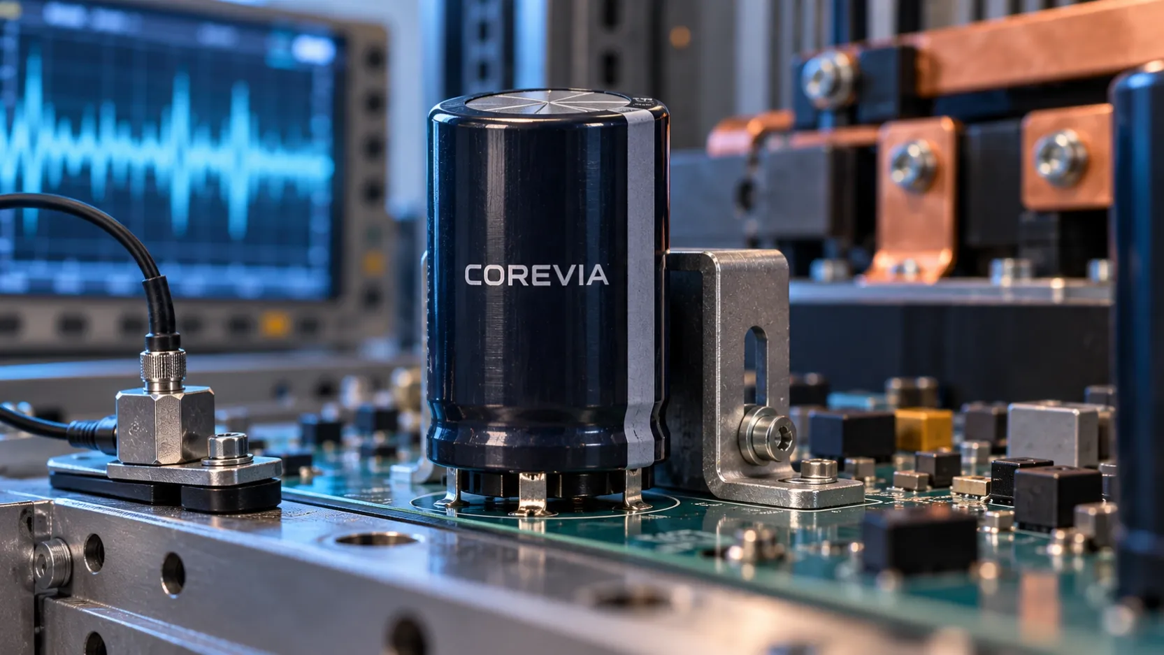
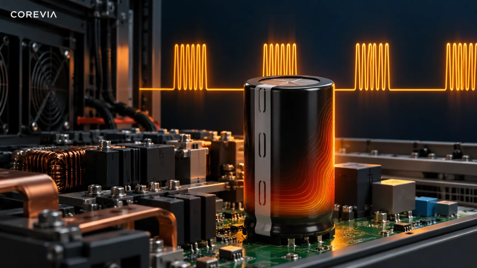
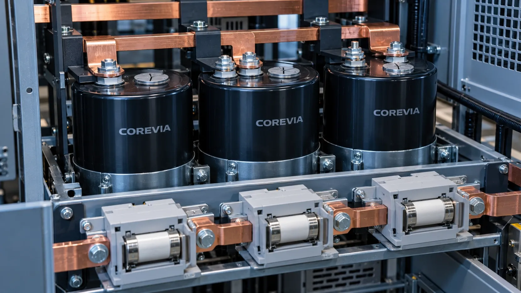
This question often arises when an OEM increases DC-link capacitance by placing several large aluminum electrolytic capacitors in parallel. The bank can meet normal voltage and ripple-current requirements while still needing a separate review of what happens if a connection or one unit fails. The cover image illustrates a protection review; it does not prescribe a wiring diagram.
What changes when capacitors share a DC link?
Parallel capacitors share the same nominal bus voltage, but current, temperature and connection resistance may differ by position. A short circuit in one location can involve energy from the supply and from the other charged capacitors. Series-parallel arrangements add another concern: a fault can change the voltage distribution across surviving sections. The consequences depend on the exact topology and the available paths for energy to flow.
Normal-operation design and fault protection are different tasks. First confirm the selected COREVIA parts meet voltage, ripple-current, temperature, endurance and mounting requirements. Then assess the credible open-circuit, short-circuit and connection faults for the assembled bank. Do not assume that a total-bank capacitance or ripple measurement proves the protection scheme is adequate.
What should the protection review document?
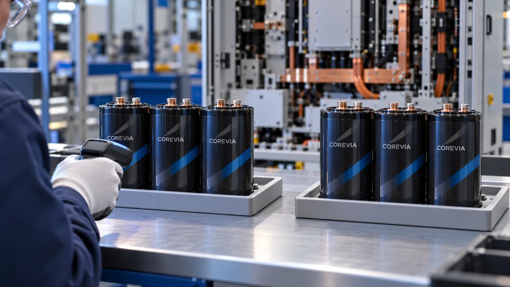
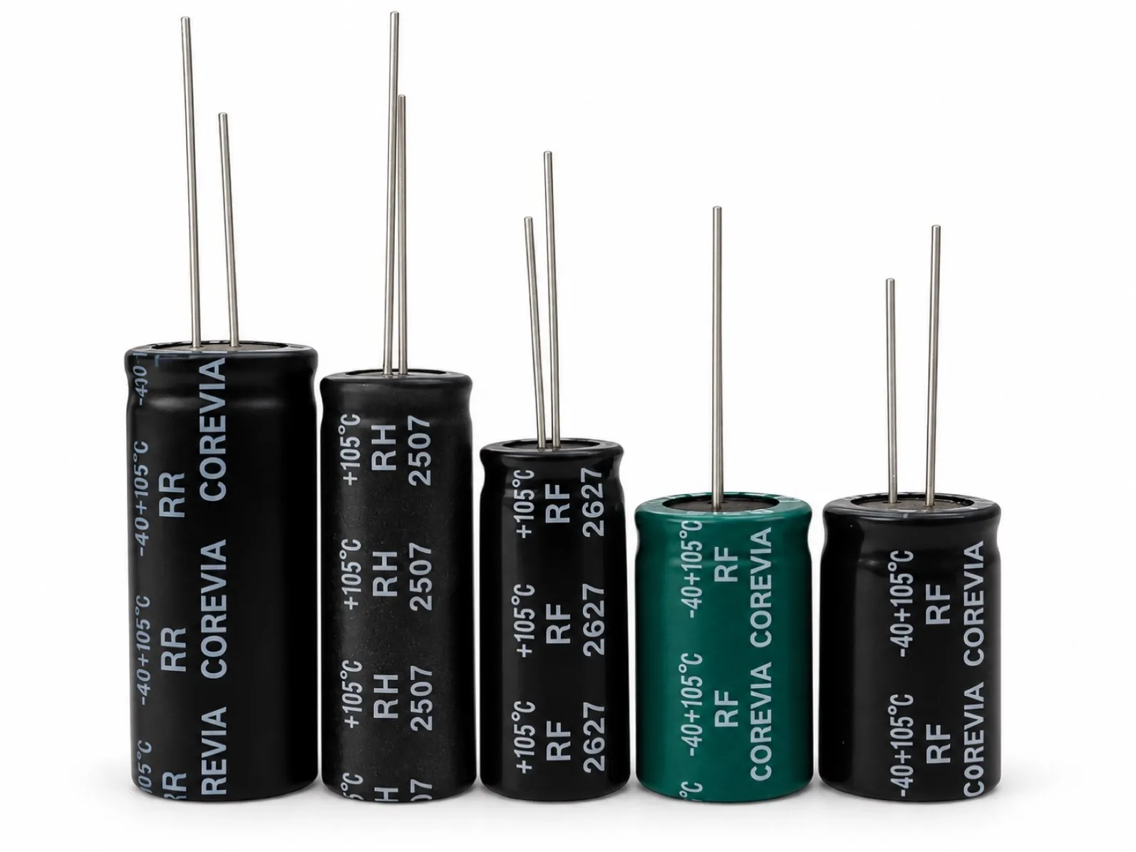
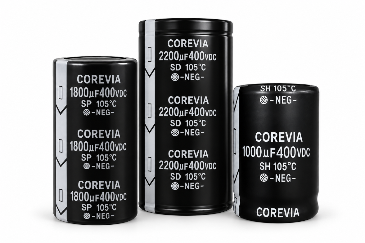
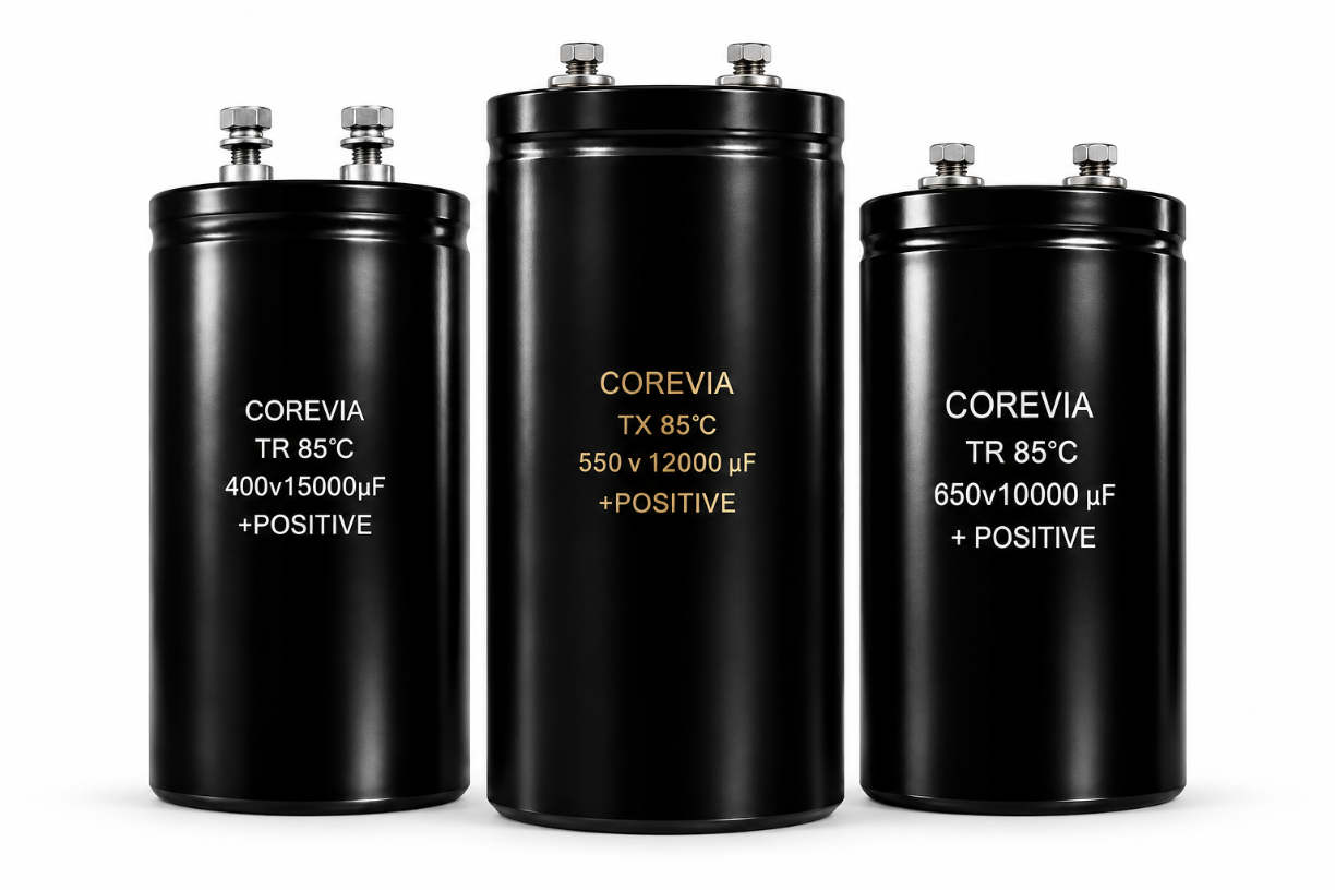
Use the actual schematic and mechanical layout. COREVIA's screw-terminal capacitor range includes large-can options used in industrial power designs, while the snap-in capacitor range has different terminals and mounting needs. A product-family page does not set fuse values or establish a universal branch-protection requirement.
| Review item | Evidence to collect | Decision it informs |
|---|---|---|
| Bank topology | Number of parallel units, any series strings and connection drawing | Identifies energy paths and affected sections |
| Capacitor selection | Exact part numbers and series limits | Confirms normal electrical and thermal operation |
| Fault sources | Supply behavior and energy stored in connected branches | Establishes credible fault exposure |
| Interconnects | Busbar or PCB geometry, cable sizes, joints and insulation | Reveals where a fault could propagate |
| Existing protection | Upstream fuses, breakers, relays and shutdown controls | Shows what is already covered and where gaps may remain |
| Proposed branch device | Device voltage, current, interrupting and thermal data for the installation | Tests whether a proposed fuse can operate as intended |
| Verification | Documented fault analysis and qualified test or simulation plan | Supports release of the final architecture |
The purpose of this table is to organize the engineering review, not to supply a fuse rating. Any protective device must be selected and coordinated against its own specification and the complete equipment. Routing, access and service procedures also matter: a disconnected source does not automatically mean the bank has discharged.
How should the final decision be made?
Compare the credible fault scenarios with the protection already provided. If an individual branch device is proposed, evaluate whether it isolates the intended fault without creating unacceptable normal-operation heating, voltage drop or maintenance complexity. If no branch device is proposed, document how the design manages the same scenarios through its topology, upstream protection and controls. Neither choice should be justified solely by a capacitor's vent feature.
For equipment context, see COREVIA's inverter application page. Share the exact part numbers, bank diagram, maximum bus conditions and proposed protective-device concept with COREVIA for capacitor-related application review. The equipment designer remains responsible for the complete fault and protection assessment.
FAQ
Is the pressure-relief vent an electrical fuse?
No. A vent provides a pressure-release path under specified abnormal internal conditions. It does not replace a device designed to interrupt a circuit fault.
Will one fuse per capacitor always prevent a bank failure from spreading?
No universal guarantee follows from the number of fuses. Fault current paths, device characteristics, placement and coordination determine whether the intended protection works in the complete assembly.
Can I choose a branch fuse from the capacitor's ripple-current rating?
No. Ripple-current rating describes a capacitor operating limit under specified conditions. Fuse selection requires a separate analysis of normal current, faults and the protective device's own ratings.
Planning a parallel DC-link bank? Contact COREVIA with the capacitor part numbers, circuit topology, busbar drawing and operating conditions so the capacitor selection can be reviewed alongside your equipment protection plan.