Can Intermittent Inverter Duty Justify Exceeding a Capacitor Ripple Current Rating?
Short inverter runs do not automatically permit excess capacitor ripple current. Check the full duty cycle, local temperature and exact COREVIA series before selection.
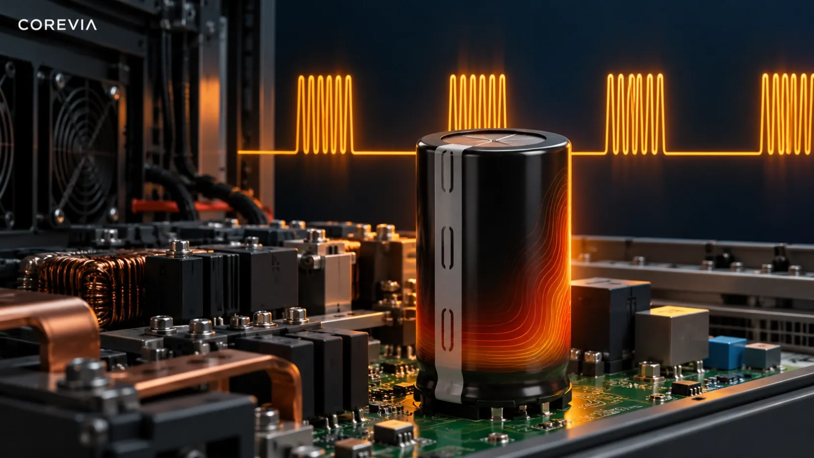
No. An intermittent inverter duty cycle does not, by itself, justify exceeding an aluminum electrolytic capacitor's published ripple-current rating. Ripple current produces internal heat, while the run time, cooling interval, ambient temperature and repeated starts determine how that heat develops in the actual equipment. Review the complete current and temperature profile against the exact COREVIA part-number specification before considering any exception. Do not apply a generic duty-cycle multiplier to a continuous rating.
An OEM should ask a more useful question: does the selected capacitor remain within its series-specific electrical and thermal limits throughout the worst repeated operating cycle? The answer needs measurements from the inverter, not just an average of nameplate load and idle time.
What does intermittent operation change?
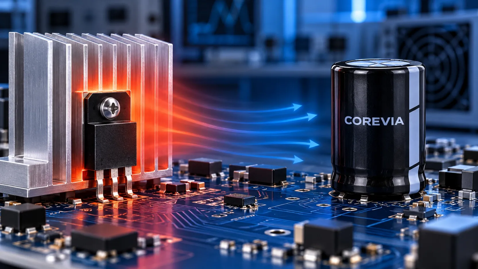
During each run, the capacitor sees the inverter's real DC-bus ripple waveform. Internal loss depends on the current and the capacitor's impedance under the relevant frequency and temperature conditions. When the load stops, the capacitor may cool, but the cooling rate depends on the cabinet, airflow and nearby hot components. A short pause should not be assumed to return the capacitor to its starting temperature.
Repeated start and stop events also deserve a separate review. They may involve charging current, voltage movement and control transitions that are not represented by a steady ripple-current value. Keep those conditions separate from the steady-load waveform when comparing candidates. An intermittent schedule is useful application data; it is not a stand-alone permission to exceed a rating.
What should be measured across the full duty cycle?
Capture the cycle after the inverter has reached its most demanding operating conditions, including the highest credible ambient temperature and a repeated sequence of runs. If several capacitors share the DC link, do not assume that a total bank-current reading proves equal current in every branch. Use a measurement plan suitable for the installed circuit and its electrical safety procedures.
| Cycle point | Evidence to record | Why it changes the decision |
|---|---|---|
| Start and acceleration | DC-bus voltage, charging sequence and capacitor-current waveform | Separates startup stress from normal ripple |
| Highest-load run | Capacitor ripple waveform, load, switching conditions and local temperature | Identifies the demanding electrical and thermal state |
| End of run | Case-area temperature and surrounding air temperature | Shows whether heat accumulated during the run |
| Cooling interval | Fan state, airflow, time and temperature before restart | Tests whether the next cycle begins from a warmer condition |
| Repeated cycles | Temperature trend and electrical readings across successive runs | Reveals whether a single-cycle check missed buildup |
| Capacitor bank | Current distribution and connection condition where measurable | Identifies a unit carrying more than its assumed share |
Record how ripple current was measured and how the result is expressed. The candidate datasheet may state its rating at a reference frequency and temperature; compare the measured waveform using the method and correction information for that exact series. A low average over the entire workday can conceal a demanding run interval.
How should an OEM compare COREVIA candidates?
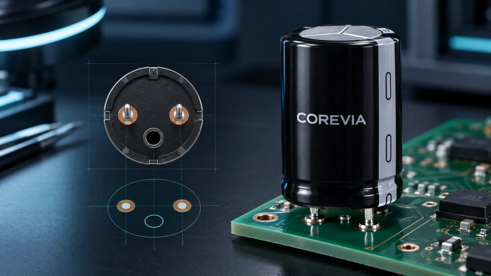
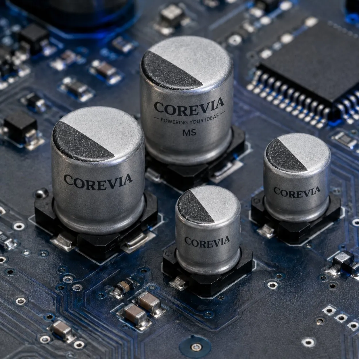
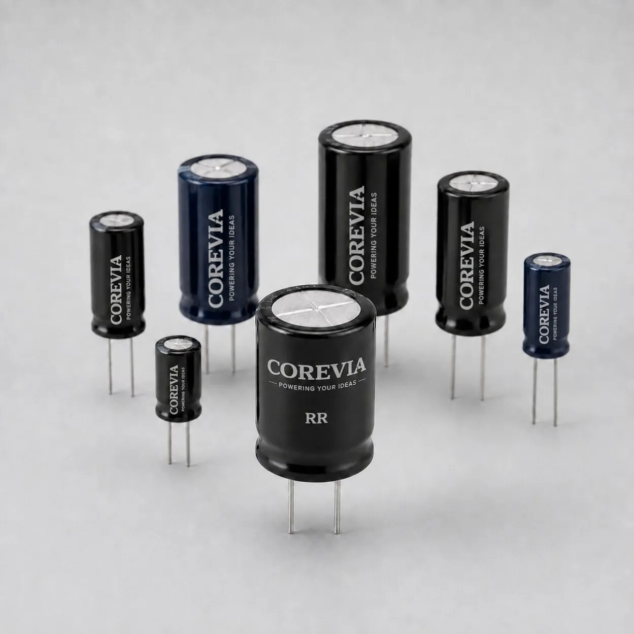
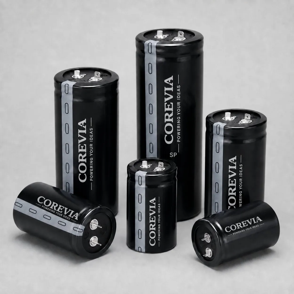
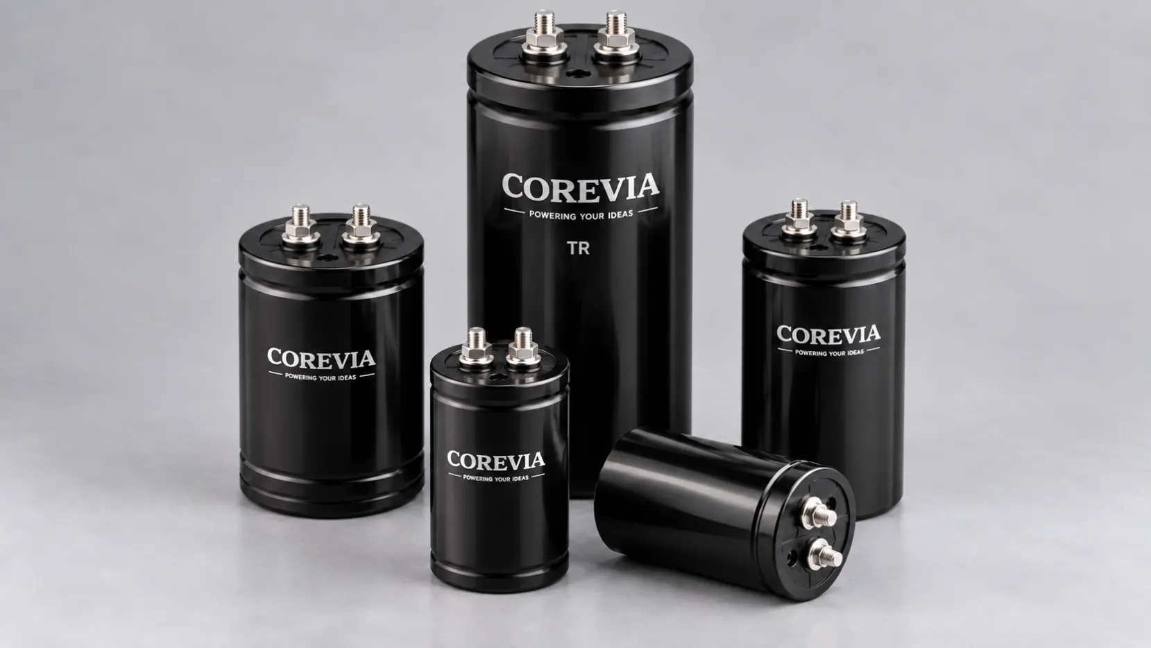
Start with the required DC voltage, capacitance and tolerance, then compare the exact part's ripple-current rating, reference conditions, operating temperature, endurance, case size, terminal layout and mounting requirements. COREVIA's snap-in capacitor range lists standard series such as SP and SH and long-endurance series such as SF and SD. Those family descriptions do not establish an intermittent overload allowance for any particular part. Large assemblies may also use the COREVIA screw-terminal capacitor range; confirm the actual part and installation details before selection.
For system context, see the COREVIA inverter application page. Send COREVIA the run and rest durations, repeated-cycle data, current waveform, voltage range, local temperature profile, cooling method, required service life and available dimensions. Contact COREVIA for a series-specific review and test plan; an application decision should be based on the measured equipment and the selected specification.
FAQ
Can I average the run current over the whole day and compare it with the datasheet rating?
No. A long idle interval can make a whole-day average look small while the capacitor experiences much higher current and heating during each run. Review the waveform and temperature across the repeated cycle using the exact series guidance.
Does a longer rest period make an over-rated run safe?
Not automatically. Cooling depends on the cabinet and airflow, and other electrical limits still apply. Measure the temperature before each restart and ask for part-specific qualification before treating a duty cycle as an exception.
Would a long-endurance series solve the ripple-current question?
Not on its own. The endurance label describes a specified test condition; it is not a blanket ripple-current upgrade. Compare the exact COREVIA part's electrical, thermal and mechanical limits against the measured inverter duty.
Reviewing an intermittent inverter design? Send COREVIA the full run/rest cycle, ripple waveform and temperature data so the exact capacitor series can be assessed for your application.