Oct 25, 2026Application Guides
How Close Can an Aluminum Electrolytic Capacitor Be to a Heat Sink?
There is no universal capacitor-to-heat-sink distance. Qualify the layout using the exact COREVIA series limits, measured temperatures, airflow and ripple conditions.
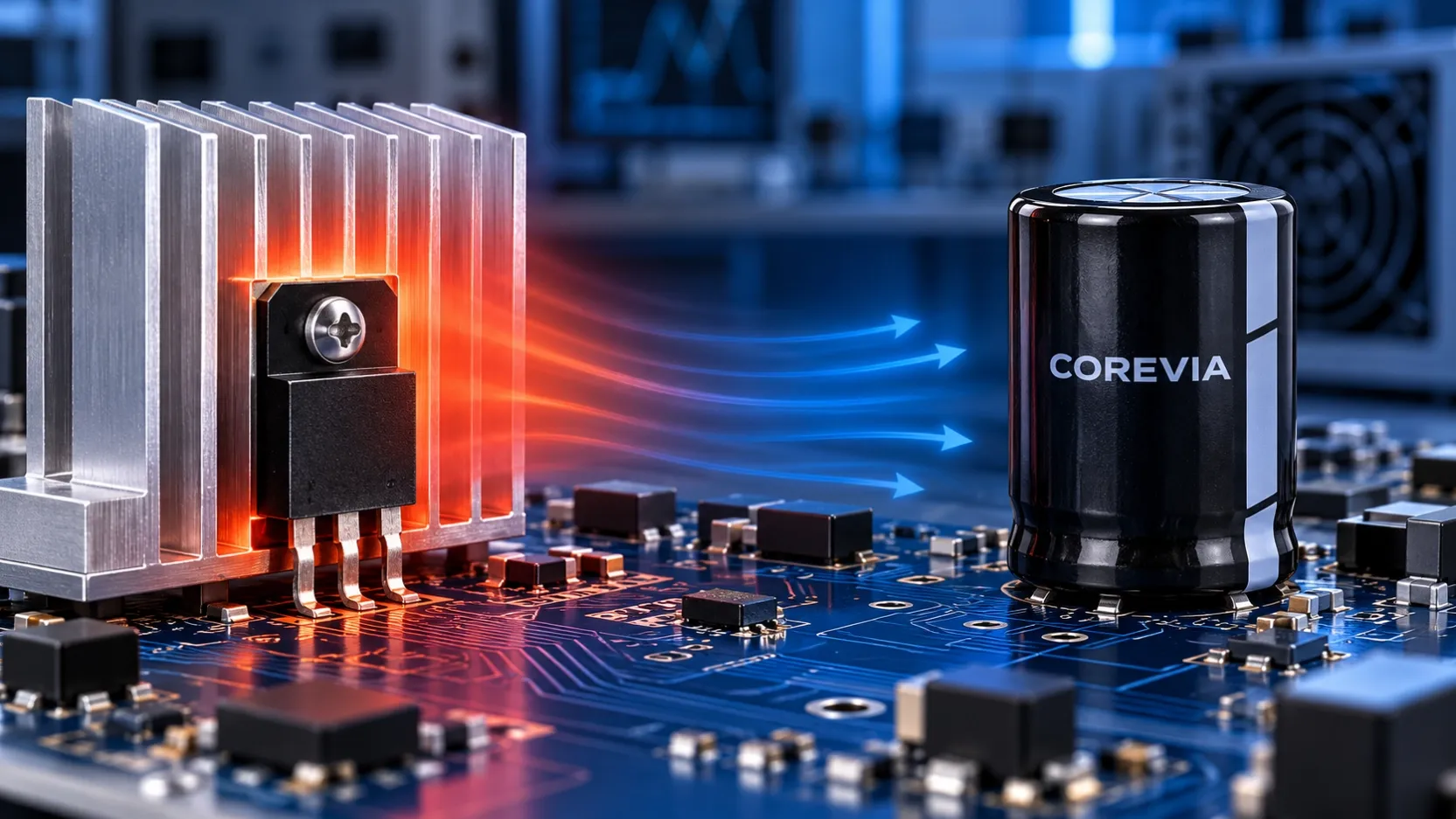
There is no universal minimum distance between an aluminum electrolytic capacitor and a heat sink. The correct spacing is the distance that keeps the exact COREVIA capacitor within its approved thermal and electrical limits under the worst credible operating condition, including local ambient heat, radiation from hot parts, heat conducted through the PCB, restricted airflow and self-heating caused by ripple current.
Do not approve the layout from room temperature, heat-sink temperature or component spacing alone. Measure the thermal condition at the capacitor location in the finished enclosure, at representative input voltage, load, cooling mode and operating orientation. Then review the result against the current specification for the complete part number.
Is there a universal capacitor-to-heat-sink spacing?
No. Two layouts with the same physical gap can expose the capacitor to different temperatures because heat-sink orientation, fin direction, airflow, PCB copper, enclosure geometry and nearby power components are different. A shield can reduce direct radiation but may also restrict airflow, so it must be validated as part of the complete assembly.
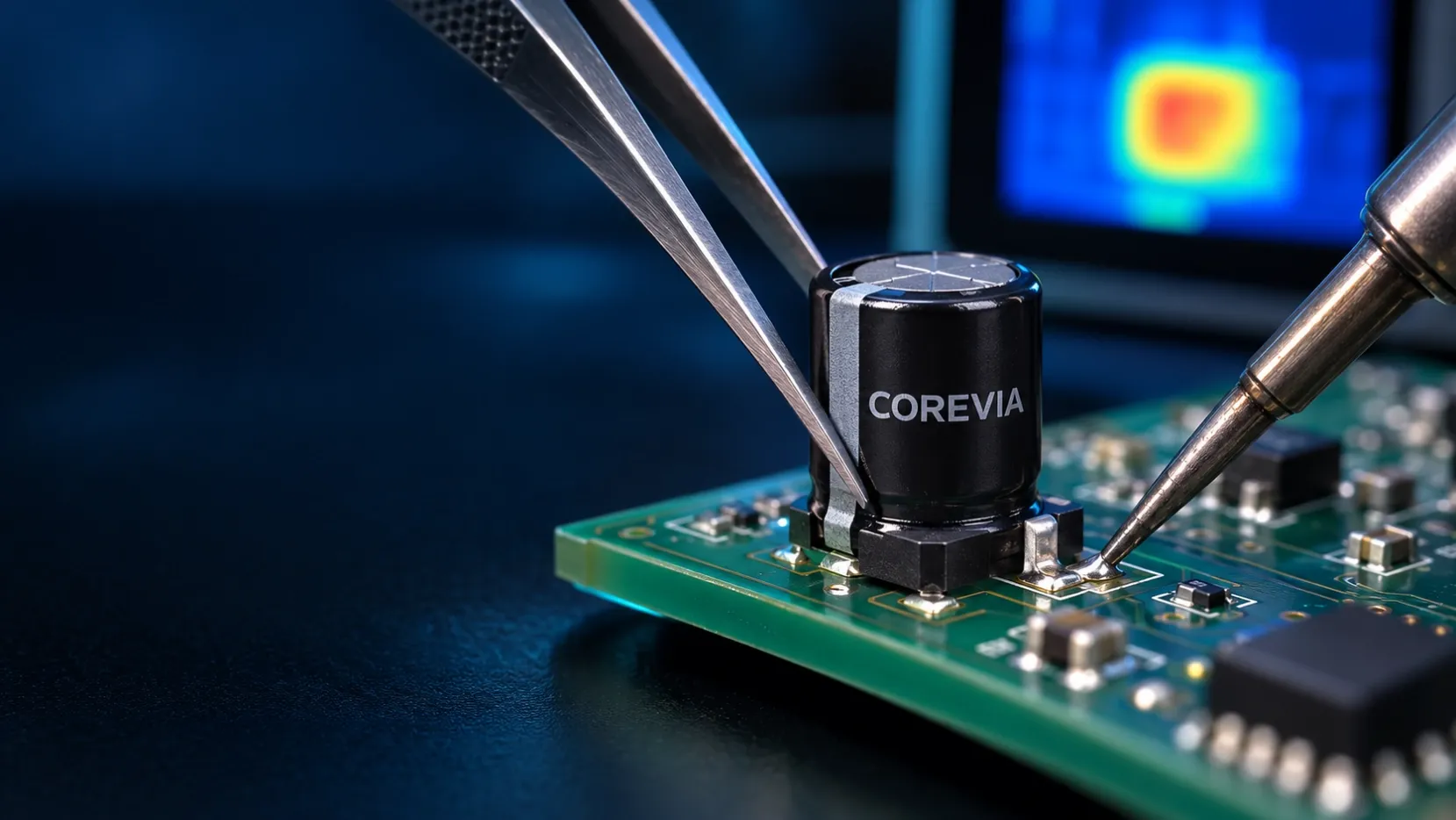
The capacitor's thermal condition is not determined only by the air entering the enclosure. Heat can reach it by convection, radiation and conduction, while ripple current adds internal temperature rise. A temperature measurement at a remote board location cannot prove the condition at the capacitor.
Keep heat-generating components away from the capacitor where practical, and avoid placing a major heat source directly behind it on the opposite side of the PCB. If the layout cannot provide comfortable thermal separation, consider moving the capacitor, changing the heat-sink orientation, improving the airflow path or selecting a COREVIA series reviewed for the actual operating conditions.
For available construction options, review the COREVIA snap-in aluminum electrolytic capacitor range. Selection must still be based on the exact series and part-number specification.
How should an OEM qualify the thermal layout?
Use a representative assembly rather than an open-board bench check. Install the normal cover, filters, fans, ducts, shields and neighboring components, then test the operating modes that can create the highest capacitor temperature.
Review item | What to verify | Why it matters |
|---|---|---|
Exact part number | Use the current COREVIA series specification and case size | Thermal limits and ripple capability depend on the exact component |
Heat-source location | Record the heat sink, semiconductor, resistor and transformer positions | Different sources transfer heat by different paths |
Airflow direction | Confirm fan mode, fin direction, obstructions and filter condition | Nominal airflow does not guarantee cooling at the capacitor |
Local temperature | Measure at the capacitor position after the assembly reaches a stable condition | Remote air or heat-sink readings may miss the local hot spot |
Ripple current | Review the actual waveform and relevant frequency components | Ripple current can add internal self-heating |
PCB conduction | Check copper areas and hot parts on both sides of the board | Heat can travel through copper and board material |
Operating range | Test credible combinations of load, input, ambient and cooling state | The thermal worst case may not occur at the nominal condition |
Production margin | Include component, fan, airflow and measurement variation | A single favorable prototype does not define the production limit |
Use temperature sensors and attachment methods that do not create a new heat path or block normal cooling. Record the sensor position, test duration and point at which the temperature has stabilized. If several capacitors share a bank, check the locations most exposed to exhaust air, radiation or restricted flow rather than assuming every position is equivalent.
Thermal qualification should be combined with the electrical review. Confirm applied voltage, ripple-current conditions, switching behavior and duty cycle for the same operating case. A cooler-looking layout is not automatically acceptable if the electrical stress remains outside the exact series limits.
What should a customer send COREVIA for review?
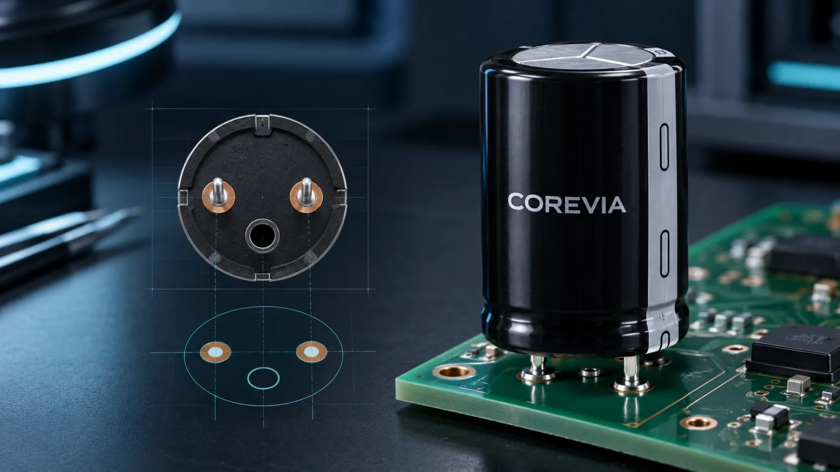
Send the complete COREVIA part number, capacitor case size, PCB layout, side view or mechanical drawing, heat-sink dimensions and orientation, nearby heat-source locations, enclosure drawing, airflow direction, fan operating modes and clear photographs of the assembled unit.
Also provide the measured local temperature, sensor location, ambient condition, time to thermal stability, applied voltage, ripple-current waveform or frequency information, load profile and expected operating life. If a shield, duct or revised spacing is being considered, include both the current and proposed layouts.
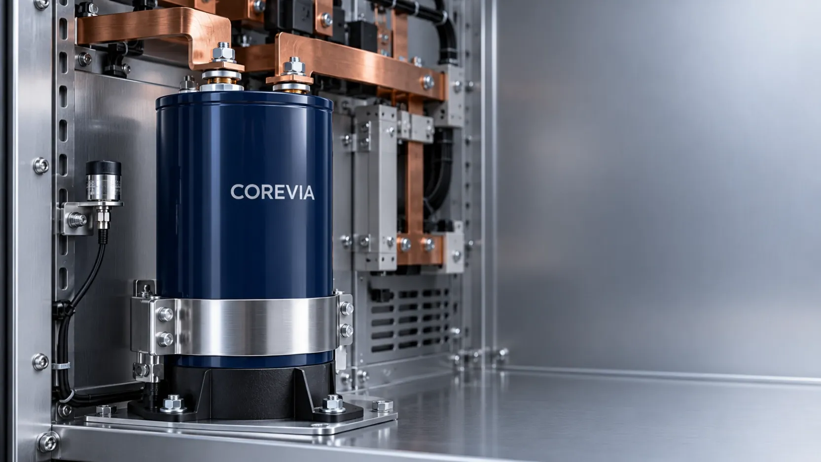
For system context, see the COREVIA inverter application page. Then contact COREVIA with the exact part number and thermal test record for an application-focused review.
FAQ
Is measuring the heat-sink temperature enough?
No. The heat-sink reading helps describe the source, but it does not establish the capacitor's local thermal condition. Airflow, radiation, PCB conduction and ripple-current self-heating must also be considered.
Can a thermal shield replace physical separation?
Not by assumption. A shield may reduce direct radiation, but it can also change airflow or trap warm air. Test the shield in the complete enclosure under the same worst-case operating conditions.
Should I measure only one capacitor in a capacitor bank?
Measure enough positions to identify the worst exposed unit. Capacitors near exhaust air, a heat source, an enclosure wall or an airflow obstruction may operate at different temperatures even when they carry similar electrical load.
Reviewing a capacitor layout beside a heat sink? Send COREVIA the exact part number, PCB and enclosure drawings, airflow path, electrical conditions and measured thermal data.