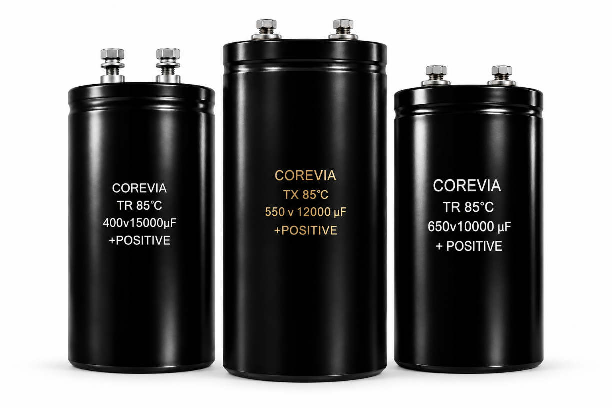
Application Guides
What Should a DC-Link Capacitor Thermal Validation Report Include?
A practical thermal validation record for COREVIA DC-link capacitors: document the exact part, load and cooling conditions, sensor positions, temperature trend and decision criteria.
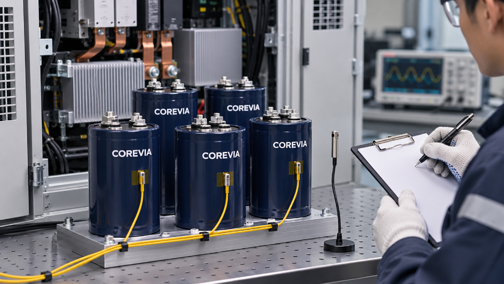
A useful DC-link capacitor thermal validation report connects the exact COREVIA part to a repeatable operating test. Record the bus voltage, capacitor-branch ripple current, enclosure airflow, local air temperature and case temperature at stated sensor locations. Show how temperatures changed from startup to the most demanding stable operating point, then compare the measured conditions with the specific series data and the limits agreed for that design. A single case-temperature number, without the load and cooling conditions behind it, cannot support a sound approval decision.
Which operating conditions must be fixed before the test?
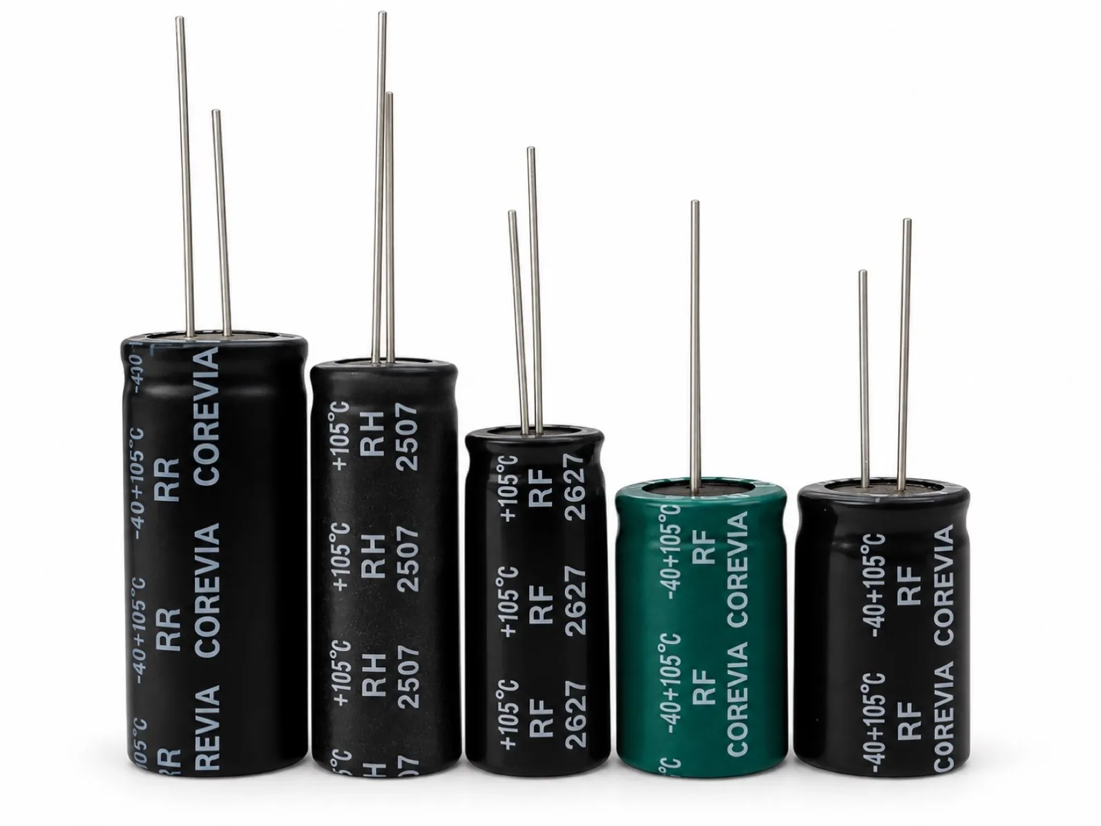
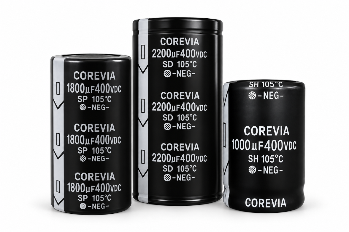
Identify the full COREVIA part number, quantity, mounting method and position in the DC-link assembly. COREVIA offers snap-in and screw-terminal aluminum electrolytic capacitor families; the test plan must use the drawing and specifications for the actual selected part. Record the bus voltage, load state, switching or line conditions, capacitor-branch current waveform, test duration, enclosure status, fan setting and the air temperature near the capacitors. State whether the test represents continuous duty, a defined overload, or a start/stop cycle.
If several capacitors share a bank, identify which unit is instrumented and why. A sensor on a convenient can does not prove that every unit sees the same current or cooling. If the design has several likely worst-case positions, measure those positions separately. Keep the electrical setup, sensor map and photographs with the report so a later production change can be compared with the tested configuration.
Where should temperature be measured and recorded?
Measure local air temperature close to the capacitor group without placing the probe in a direct hot exhaust stream unless that is the actual exposure. Fix each case sensor to a documented, repeatable point on the can without blocking the pressure-relief vent or changing the cooling path. Record the sensor type, attachment method, logger interval and calibration status. For screw-terminal units, a separate terminal or busbar-joint reading can help distinguish connection heating from can heating, but it does not replace the case-temperature record.
Capture the temperature trend rather than only the final reading. Note startup, load changes and the point at which readings stabilize under the defined duty. Where the application cycles, report the relevant peaks and repeatability across cycles. Surface readings are not a direct measurement of internal core temperature; use the exact series guidance and an agreed engineering method when estimating internal thermal stress or life.
What evidence belongs in the approval record?
Record | Why it matters | Evidence to retain |
|---|---|---|
Exact part and installation | Ties the result to the approved COREVIA configuration | Part number, drawing revision and assembly photo |
Electrical duty | Shows what caused internal heating | Bus voltage and capacitor-branch current waveform |
Cooling and local air | Makes the thermal boundary reproducible | Enclosure, fan and nearby air-probe record |
Case and connection temperature | Separates capacitor and joint observations | Sensor map and time-stamped trends |
Decision rule | Explains release or redesign | Exact series limits, agreed test criteria and reviewer sign-off |
Do not borrow a temperature-rise allowance or lifetime multiplier from a different product family. If the result is close to a limit, investigate sensor placement, current sharing, airflow and test uncertainty before making a pass/fail claim. Keep the raw trend and the final decision together. If a part change, cooling change or busbar revision alters the tested boundary conditions, assess whether the validation must be repeated.
FAQ: DC-link capacitor thermal validation
Is one thermal-camera image enough for approval?
No. An image can help locate a hot area, but the report still needs the exact part, electrical duty, cooling state, calibrated temperature record, sensor locations and an applicable decision rule.
Can case temperature alone predict capacitor lifetime?
No. Case temperature is a useful observation, but it is not the internal core temperature. Lifetime assessment requires the exact part information and a method appropriate to the actual voltage, ripple and thermal conditions.
Should every capacitor in a parallel bank be instrumented?
The sampling plan depends on layout and risk. Measure locations that could see different current or cooling, and document why the selected points represent the bank. If the data show imbalance, expand the measurements before approval.
For a part-specific review, compare COREVIA capacitor families and contact COREVIA with your full part number, electrical duty, enclosure drawing and proposed sensor map.