Sep 25, 2026Application Guides
Choosing Between Snap-in and Screw Terminal Capacitors
Compare electrical demand, mounting method, case size and service conditions when selecting snap-in or screw terminal capacitors.
Choosing Between Snap-In and Screw-Terminal Capacitors
Snap-in and screw-terminal aluminum electrolytic capacitors can both serve high-energy DC-link applications, but they are designed for different mounting, current and service conditions. The choice should follow the converter requirements and mechanical design rather than a simple rule based on capacitance or voltage.
Start with the electrical duty. Record the maximum continuous DC voltage, transient conditions, required capacitance, allowable DC-bus ripple and the RMS ripple-current spectrum. Compare ripple-current ratings only at the stated frequency and temperature. ESR or impedance must also be reviewed because internal heating is related to ripple current and ESR. A physically larger capacitor is not automatically a better electrical match.
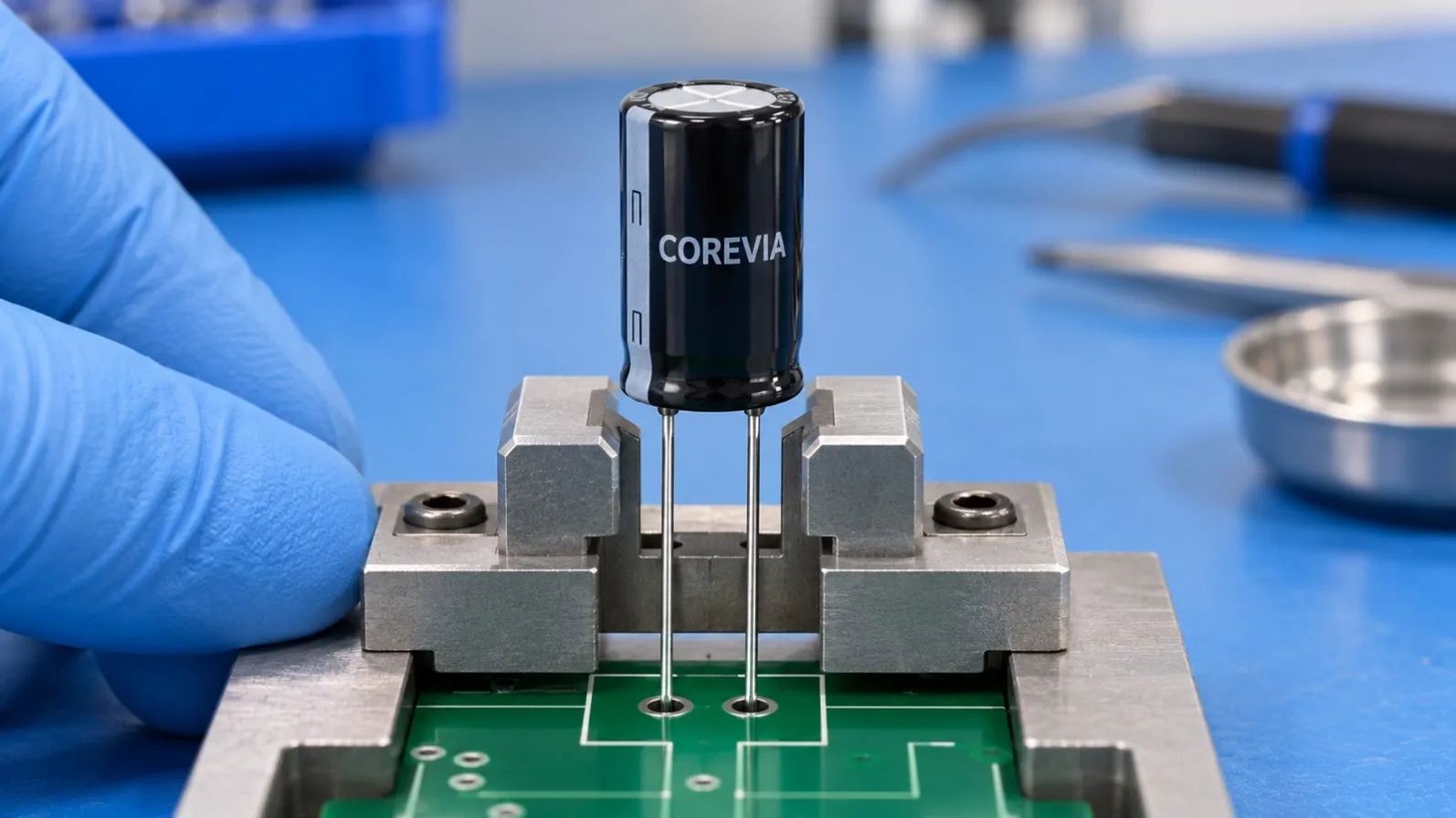
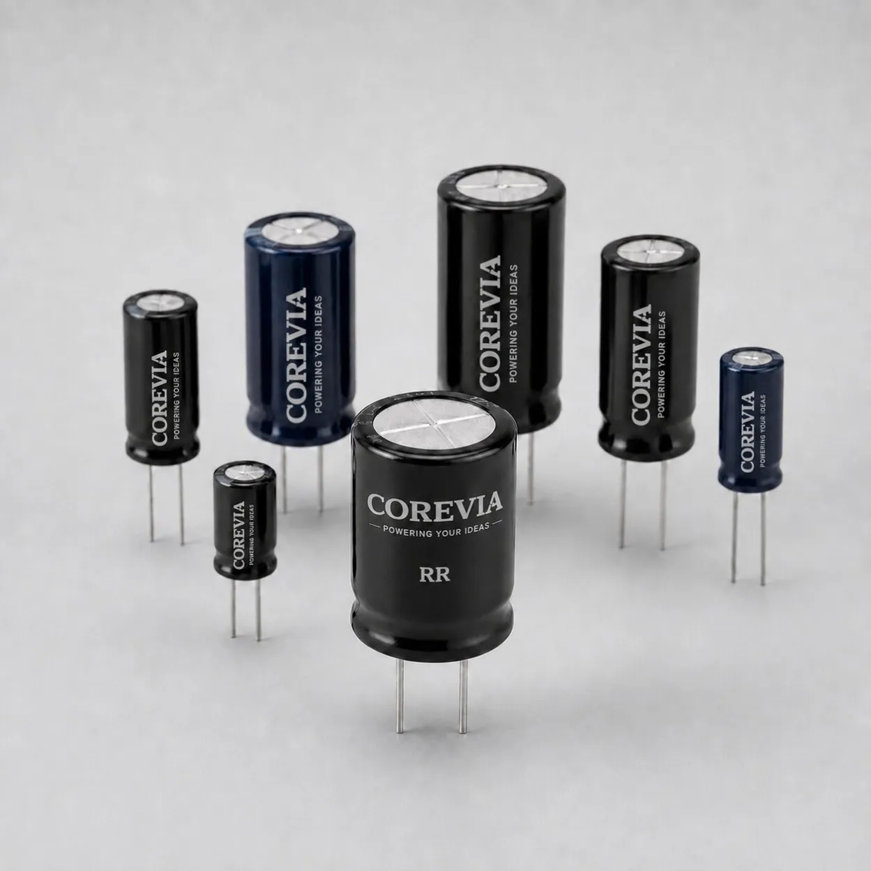
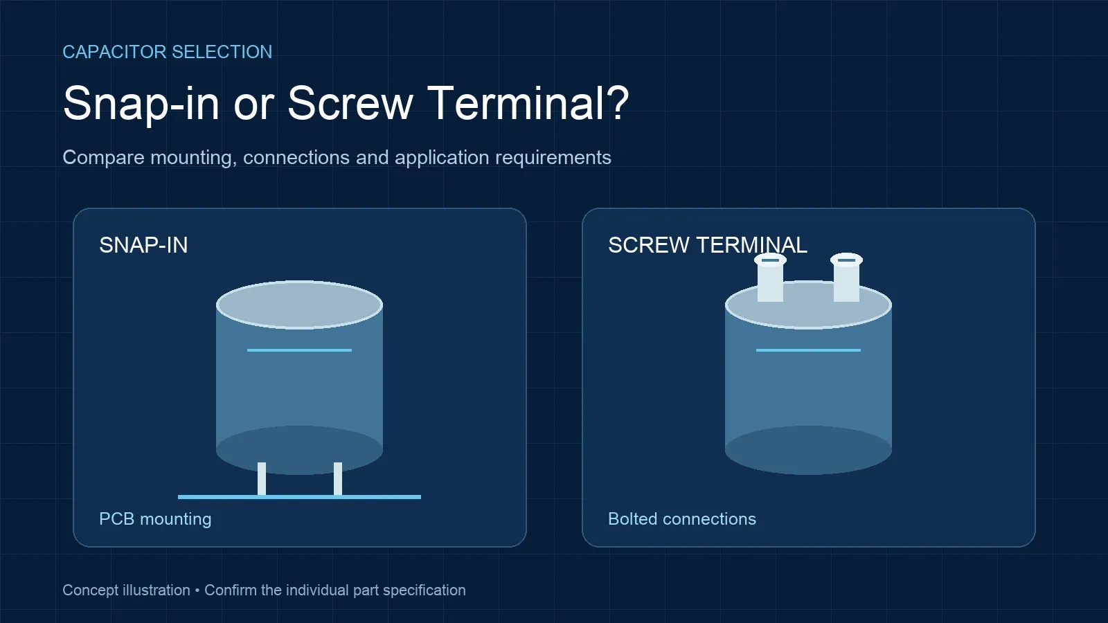
Snap-in capacitors mount directly to a printed circuit board. They are useful where compact assembly, short current paths and automated or controlled board production are priorities. Confirm lead spacing, case diameter, case height, polarity, PCB hole size and the mechanical support available to the board. The capacitor safety vent needs clear space, and heavy components should not depend on solder joints alone when the equipment is exposed to shock or vibration.
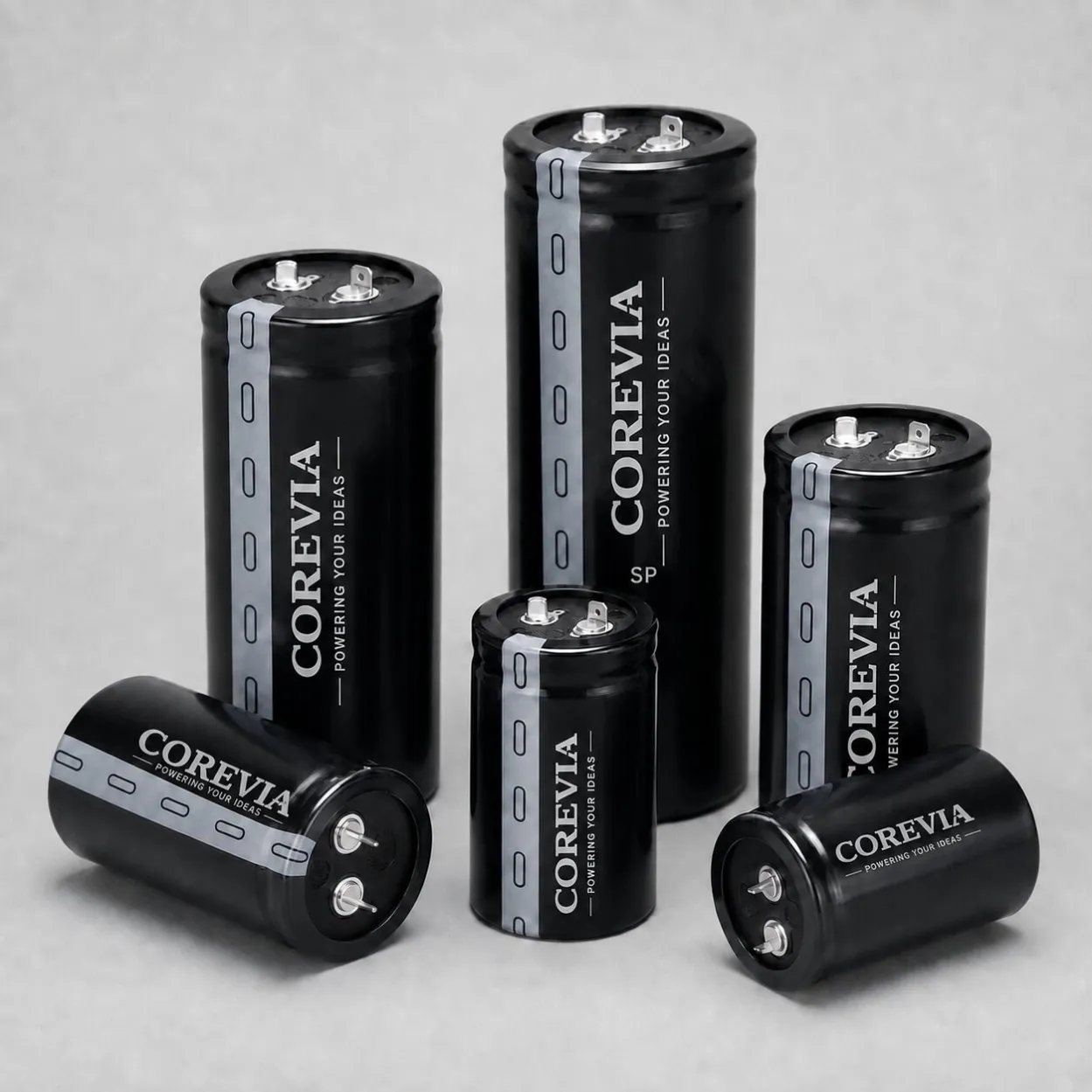
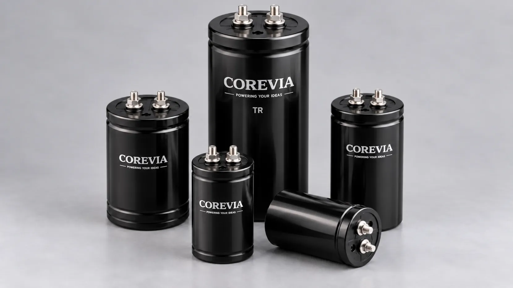
Screw-terminal capacitors use threaded terminals and are commonly connected with busbars or cables. This construction suits serviceable DC-link banks, higher capacitance requirements and applications where the connection layout must carry substantial current. Confirm the terminal thread, permitted torque, washer and busbar arrangement, polarity, insulation distance, clamp method and vent clearance. Busbars must align naturally; forcing them into position can stress the terminal or seal.
Bank design can determine the better format. Parallel capacitors need similar conductor length and connection resistance so ripple current divides evenly. An asymmetric busbar can make one part run hotter even when all capacitors have the same part number. For series-connected banks, check voltage-sharing components, leakage-current behavior and voltage distribution under normal, standby and transient conditions.
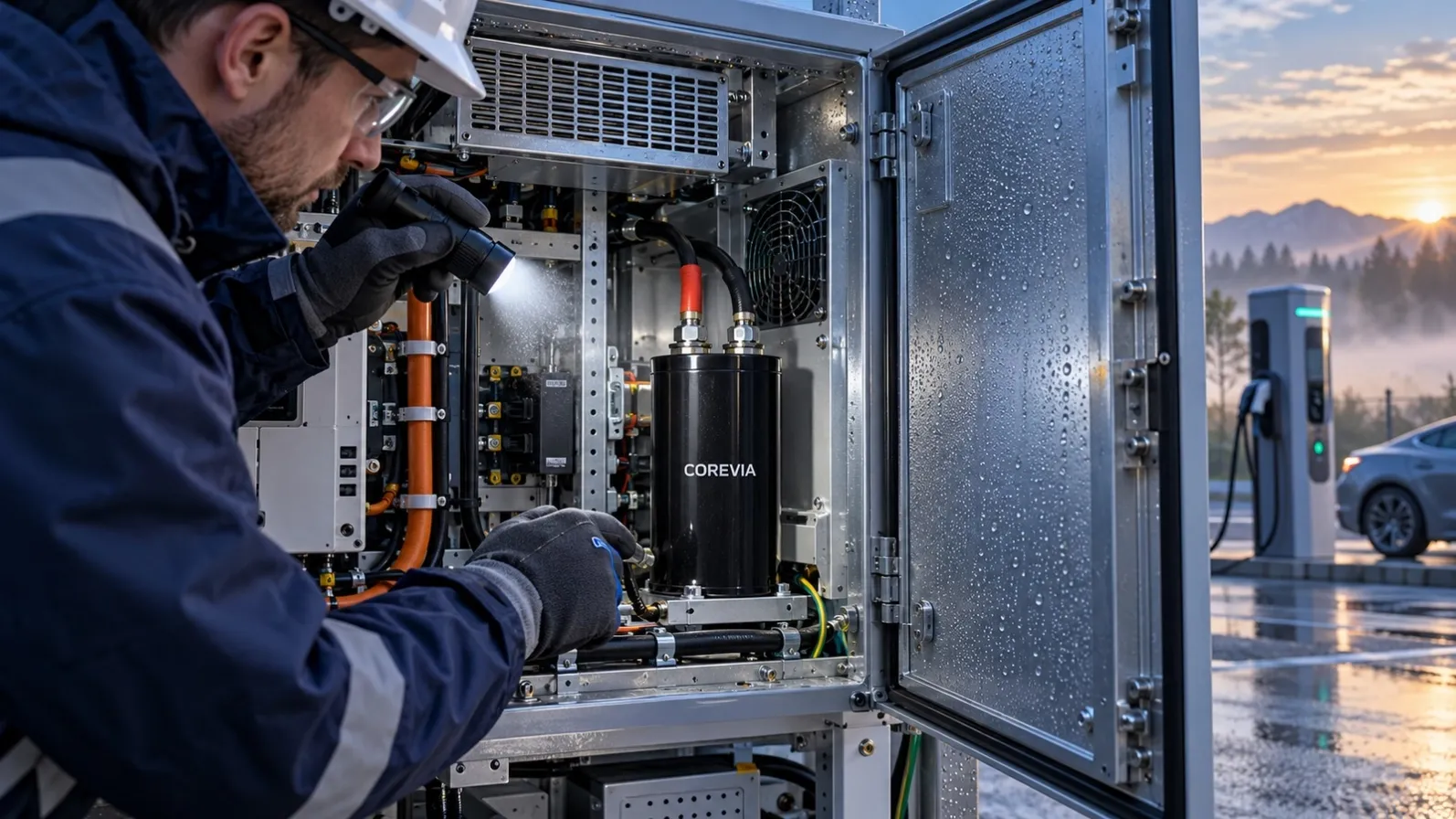
Thermal conditions are equally important. Identify the maximum ambient temperature, airflow, nearby heat sources and the expected capacitor hotspot. Snap-in parts mounted close to switching devices or heat sinks may experience higher local temperature than the enclosure sensor shows. Screw-terminal banks can also develop connection hot spots from loose hardware, oxidation or uneven contact pressure. Temperature measurements should cover representative load and cooling modes.
Endurance figures are test results under defined voltage, ripple-current and temperature conditions. They are not direct guarantees of equipment service life. Compare the full operating profile, including annual hours, high-load duration, start-stop cycles, cooling interruptions and maintenance expectations. If the application has repeated pre-charge events, verify the resistor, contactor sequence and timing for the selected bank.
Mechanical service requirements can be decisive. A PCB-mounted snap-in design can reduce wiring and volume, while a screw-terminal bank may simplify inspection and individual component replacement. Review enclosure access, discharge procedure, touch protection, clamp location and whether the bank can be assembled without placing load on terminals or the PCB.
COREVIA offers eight snap-in series—SP, SH, SS, SC, SF, SU, SD and SZ—and eleven screw-terminal series—TR, TT, TX, TF, TK, TG, TN, TM, TD, TH and TA. Compare only the confirmed series data for voltage, capacitance, temperature and endurance; do not treat the total portfolio range as the specification of one representative series.
For a selection review, provide the DC-bus voltage, capacitance target, ripple-current frequency and RMS value, ambient and hotspot temperature, case limits, mounting layout, terminal requirements, bank configuration, expected quantity and application. Send these details to [email protected] so the relevant snap-in or screw-terminal series can be checked without assuming missing requirements.