Sep 26, 2026
Common Causes of Aluminum Electrolytic Capacitor Bulging and Premature Failure
A practical guide to electrical, thermal and installation conditions that can cause aluminum electrolytic capacitor bulging or premature failure.
Common Causes of Aluminum Electrolytic Capacitor Bulging and Premature Failure
Bulging is a visible warning that an aluminum electrolytic capacitor may have experienced internal pressure, abnormal heating or mechanical deformation. It should not be treated as a cosmetic issue. De-energize the equipment using the approved service procedure, allow the DC bus to discharge, verify the remaining voltage and investigate the system before replacing the part.
Electrical overstress is one common cause. Continuous voltage above the capacitor rating, repeated transients, incorrect series voltage sharing or reverse polarity can increase leakage current and gas generation. Check the maximum voltage across the individual capacitor rather than only the nominal system bus. For series-connected capacitors, measure voltage distribution and inspect balancing resistors, connection integrity and leakage-current differences.
Excess ripple current can create internal heat even when the average DC voltage is acceptable. Ripple loss depends on RMS current and ESR, and ESR varies with frequency and temperature. Measure the ripple waveform under representative load and operating modes. A handheld meter may not capture high-frequency components accurately, so use suitable bandwidth, probes and safe measurement practices. Compare the result with the capacitor data under the same frequency and temperature conditions.
High ambient temperature and poor cooling accelerate electrolyte loss and can raise the internal hotspot. Look for blocked airflow, failed fans, dust, nearby heat sources, tight spacing and recirculating hot air. Measure temperature near the capacitor case after the equipment reaches thermal stability. The hottest condition may occur during charging, overload, low fan speed or another duty cycle rather than during a short bench test.
Connection problems can concentrate heat outside or inside the capacitor. Loose screw terminals, oxidized joints, uneven busbar pressure, cracked solder joints and undersized conductors can create local resistance. Inspect for discoloration, softened insulation, damaged hardware or a temperature difference between equivalent connections. Follow the equipment and capacitor torque requirements; excessive torque can also damage a terminal or seal.
Incorrect pre-charge behavior can expose a DC-link capacitor to severe inrush current. Check the pre-charge resistor, contactor sequence, timing, control supply and any bypass path. If a replacement capacitor fails soon after installation, confirm that the system is not repeatedly connecting a discharged bank directly to the source.
Storage and long idle periods require separate consideration. The oxide layer in an aluminum electrolytic capacitor can degrade during extended storage, increasing leakage current during initial energization. Follow the capacitor manufacturer’s storage and reforming guidance when available. Do not improvise a reforming procedure without appropriate current limiting, voltage control and safety measures.
Mechanical damage can resemble pressure-related bulging. Clamps, brackets, mounting force, impact or distorted busbars may deform the can or bottom plate. Compare the observed shape with the capacitor construction and inspect the safety vent, seal and mounting surface. Local side deformation, a lifted terminal cover and an opened pressure vent point to different failure mechanisms and should be documented separately.
When investigating a failed unit, record the complete part number, production information, operating hours, failure time, load condition, ambient temperature, bus voltage, ripple current, bank configuration and photographs from several angles. Inspect related fuses, contactors, resistors, cooling components and neighboring capacitors. In a parallel bank, test each branch because the total bank capacitance can hide one disconnected or weak unit.
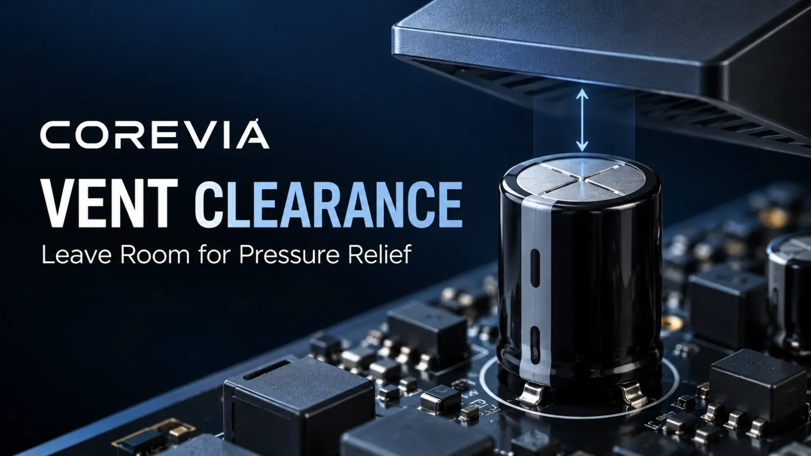
Do not restart equipment simply because the bulged capacitor has been replaced. Correct the confirmed cause, verify polarity and connections, inspect insulation and vent clearance, and use a controlled commissioning sequence. Monitor bus voltage, current and temperature during the first operating period.
For replacement review, send the existing part number, datasheet, voltage, capacitance, ripple conditions, case dimensions, terminal style, application and clear failure photographs to [email protected]. Fault photographs should be treated as diagnostic evidence and should not be presented as branded product photography.