Sep 26, 2026
Capacitors for Energy Storage Systems
How to select aluminum electrolytic capacitors for energy-storage converters using voltage, ripple current, ESR, temperature, cooling and endurance.
Capacitors for Energy Storage Systems
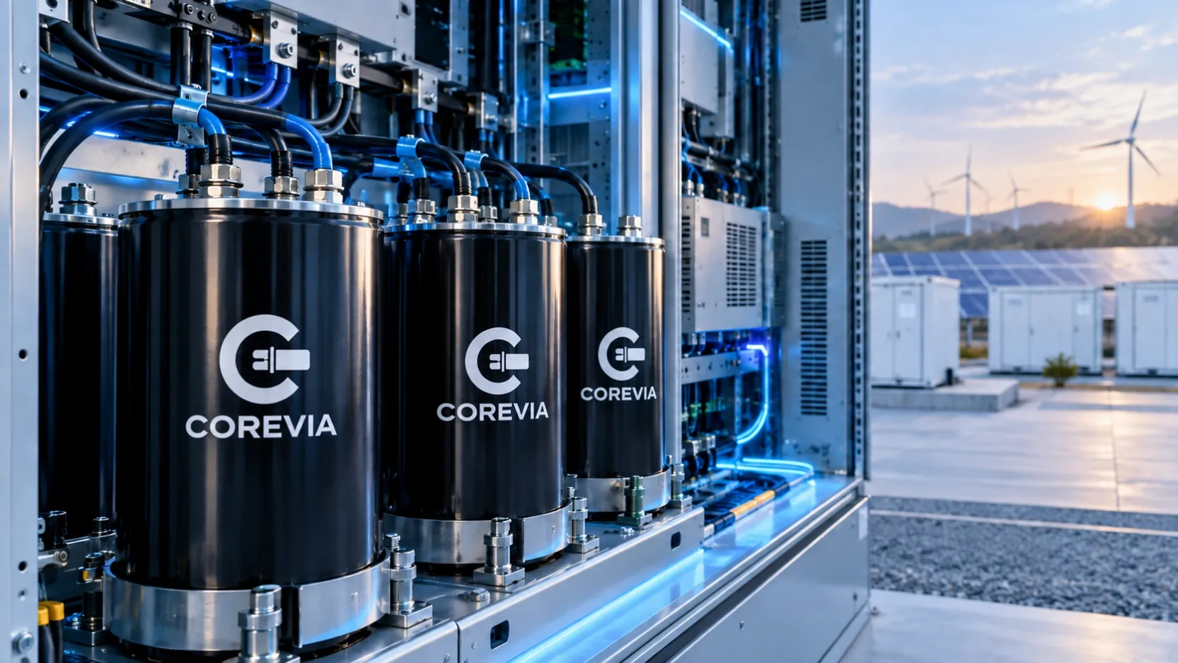
Aluminum electrolytic capacitors in an energy-storage converter usually work in the DC-link section between the battery, rectifier, inverter or bidirectional power stage. Their job is to stabilize the DC bus, absorb ripple current, support short transient power demands and reduce the voltage disturbance seen by switching devices. Selecting them only from bus voltage and capacitance can overlook the stresses that control temperature and endurance.
Start with the real DC-bus voltage. Use the highest continuous voltage expected across operating modes and include charging tolerances, regeneration, grid variation and control overshoot. The capacitor rating needs suitable margin for the actual system, but a higher printed voltage alone does not prove suitability. Higher-voltage parts may use a different case size, ESR profile or capacitance range, so the full design must be compared.
Capacitance is normally set by allowable bus ripple, transient energy and control requirements. The required value depends on topology, switching frequency, load steps and the amount of energy the battery or upstream converter can deliver during a transient. Check minimum capacitance after tolerance and expected aging rather than relying only on the nominal label. For series strings, consider capacitance tolerance and voltage-sharing behavior across every position.
Ripple current is often the main thermal load. Separate low-frequency ripple caused by rectification or power flow from high-frequency switching components. The RMS total and its frequency distribution matter because ESR changes with frequency and temperature. Compare candidate ripple-current ratings only after confirming the datasheet frequency and temperature conditions. A value published at 105 °C and 100 or 120 Hz cannot be compared directly with a value published under different conditions without the manufacturer’s correction data.
Internal heating is related to ripple current and ESR. As a practical screening relationship, ripple loss rises approximately with the square of current multiplied by ESR. This means a modest increase in RMS ripple can produce a much larger increase in heat. Estimate the capacitor hotspot from ambient temperature, airflow, thermal coupling, case size, mounting and nearby components. Measure operating temperature during representative charging, discharging, standby and overload conditions.
Energy-storage systems also create repeated pre-charge and discharge events. Review inrush limiting, pre-charge resistor value, contactor timing and the residual voltage present before reconnection. A capacitor that meets steady-state ripple requirements can still be exposed to damaging current if the pre-charge sequence is bypassed or a contactor closes too early. Discharge resistors and service procedures must leave the DC bus at a controlled voltage before maintenance.
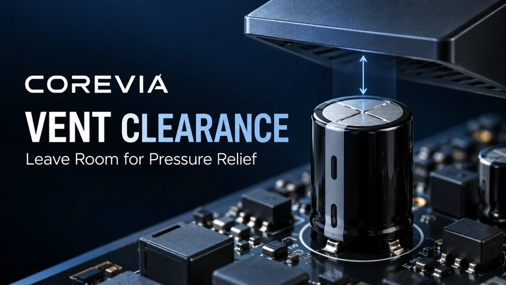
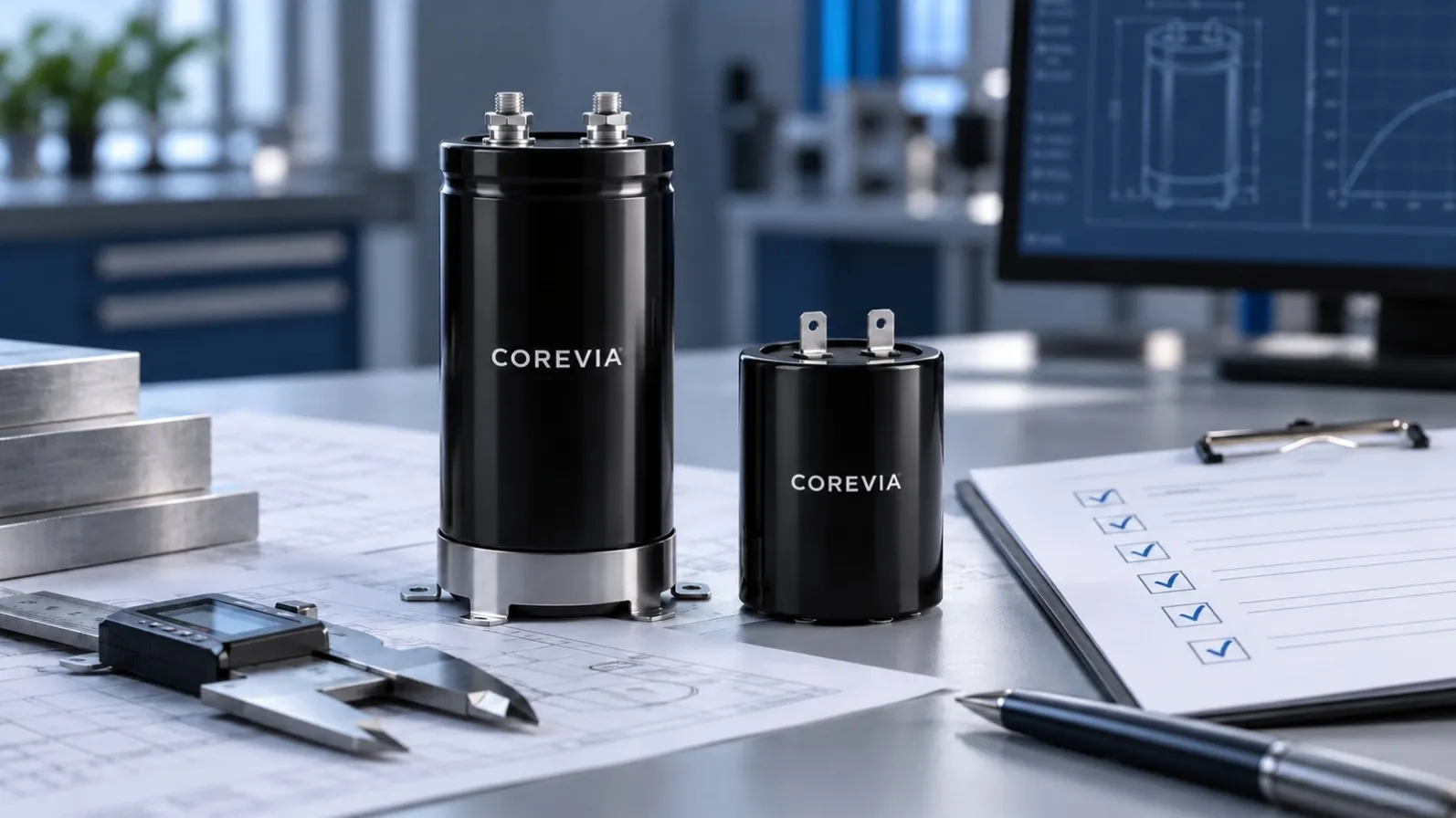
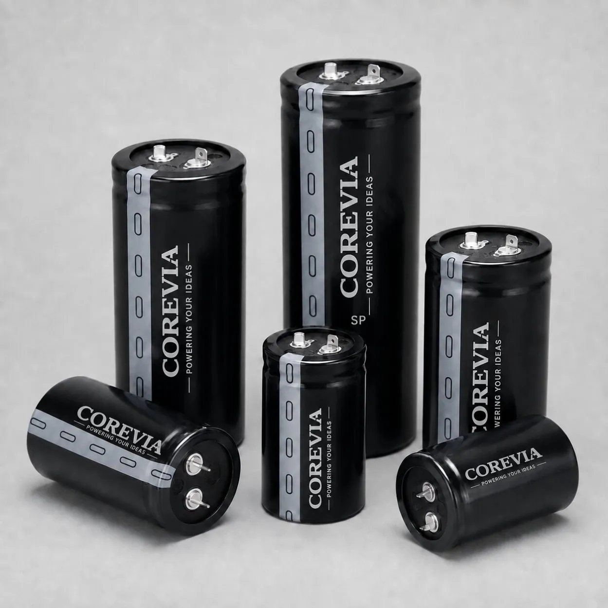
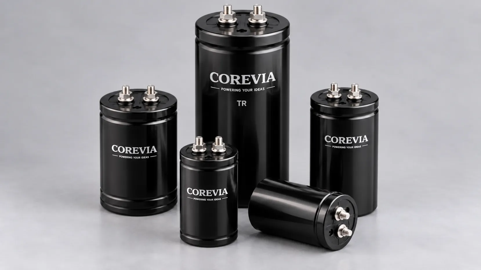
Choose the construction around the required power and serviceability. Snap-in capacitors suit compact PCB-mounted DC links when board layout, lead spacing and vent clearance are controlled. Screw-terminal capacitors are used where higher capacitance, robust busbar connections or serviceable bank construction is needed. The final choice depends on verified electrical and mechanical limits; the terminal style alone does not determine performance.
For parallel banks, aim for symmetrical busbar geometry and similar connection resistance. Small differences in conductor length, joint resistance or temperature can shift ripple current toward one capacitor. Verify torque requirements for screw-terminal connections and inspect joints for discoloration or local heating. In a series string, review balancing components and leakage-current behavior, then confirm voltage distribution under normal and standby conditions.
The endurance figure on a datasheet is a defined test condition, not a direct prediction of system life. Evaluate voltage, ripple current, hotspot temperature and operating profile together. Record the duty cycle, maximum ambient temperature, enclosure cooling, annual operating hours and maintenance expectations. These inputs allow a more meaningful comparison between candidate series.
For a selection request, provide the DC-bus voltage range, capacitance target, ripple-current spectrum or switching frequency, ambient and measured hotspot temperature, case limits, terminal arrangement, bank configuration, expected quantity and application. COREVIA can then review relevant snap-in and screw-terminal aluminum electrolytic capacitor series without assuming missing requirements.