Oct 12, 2026Reliability Engineering
Capacitor Voltage Rebound After Discharge: What to Check
Why can an aluminum electrolytic capacitor show voltage again after discharge? Learn to distinguish recovery voltage from backfeed in UPS and inverter service.
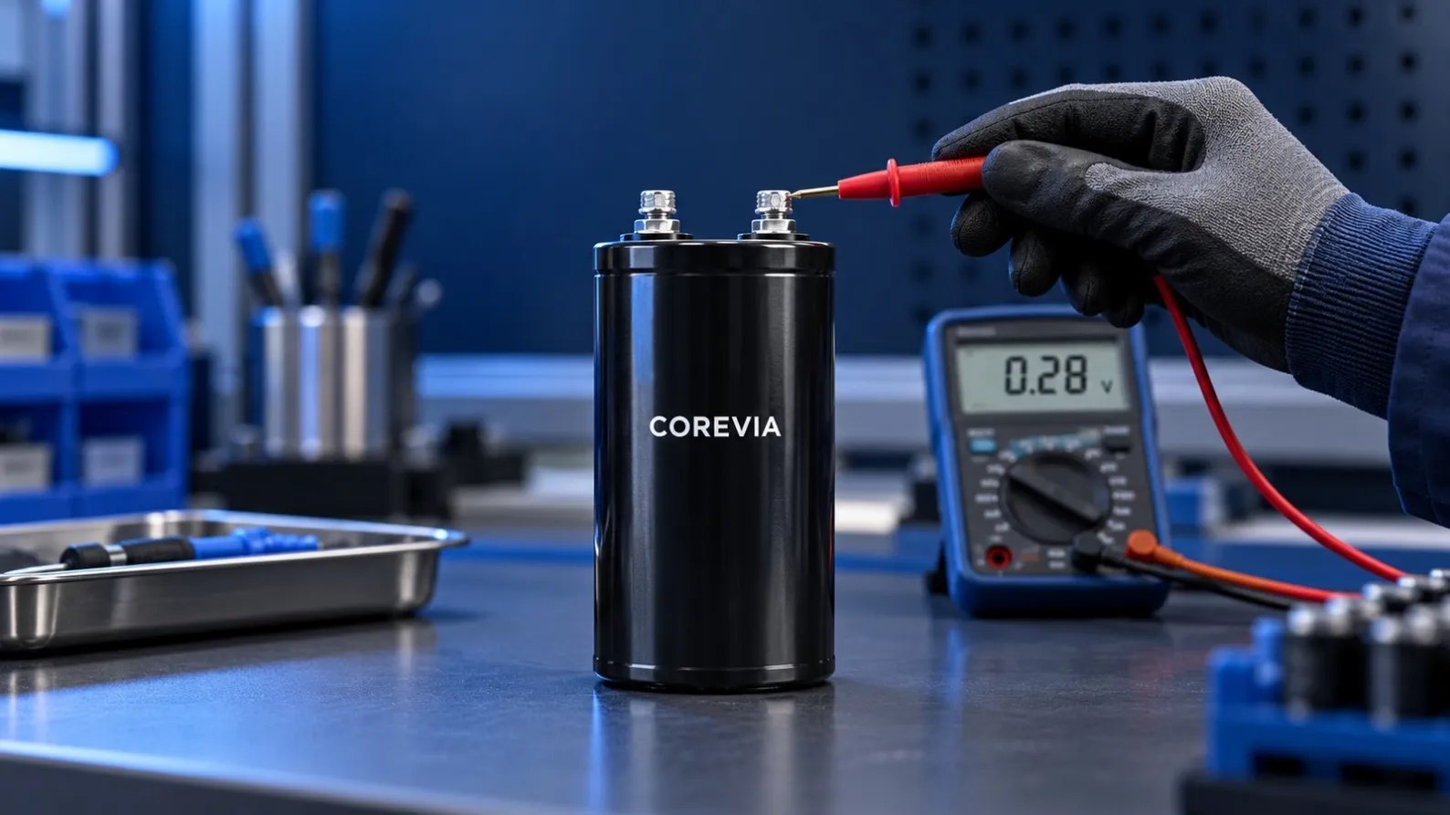
A UPS is switched off. The DC-link capacitor is discharged and the meter reads near zero. A little later, a voltage appears across its terminals again. Did the discharge circuit fail?
It might have. But a charged aluminum electrolytic capacitor can also develop recovery voltage after discharge. In field service, the important step is to tell that effect apart from voltage supplied by another part of the equipment.
Why can the voltage return?
Charge does not always redistribute instantly within a capacitor's dielectric. After the terminal voltage has been reduced and the part is left open, a portion of the earlier charge can appear again at the terminals. This is commonly called recovery voltage or voltage rebound. Its size and timing depend on the capacitor and its history; a single reading cannot predict what will happen next.
Recovery voltage does not mean the capacitor has recharged itself with new energy from the mains. It does mean that a quick zero-volt check is not enough evidence for handling it.
Recovery voltage or backfeed?
In a UPS, inverter, VFD or energy-storage converter, a voltage reading can have another explanation. A battery, auxiliary supply, connected module or shared DC bus may still be feeding the circuit. A failed discharge path can leave stored energy in the bank as well.
If the capacitor is still installed, never assume a rising reading is only recovery voltage. Confirm all energy sources and the equipment's isolation and discharge sequence using its service procedure. A reading directly across the capacitor terminals tells you more than a reading taken somewhere else on the bus.
What should the service team record?
- The voltage directly across the capacitor at the first check and at later checks, with the elapsed time noted.
- Whether the capacitor was isolated or remained connected to the circuit.
- The state of batteries, auxiliary supplies, parallel modules and contactors.
- The discharge path and any relevant service records.
- The capacitor part number, rated voltage and capacitance.
Use a meter and method rated for the equipment. Follow lockout, isolation and discharge instructions before any contact with terminals. Do not bridge terminals with a tool to make a spark; that can damage components and is not a reliable verification method.
The practical takeaway
A returned voltage reading is a clue, not a diagnosis. On an isolated capacitor, recovery voltage may explain it. In installed equipment, backfeed or incomplete discharge must also be investigated. Time-stamped readings and a clear circuit diagram help the service team find the real cause without replacing a good capacitor unnecessarily.
Need help reviewing a capacitor application? Send COREVIA the part number, equipment type, circuit arrangement and measured readings.
COREVIA — Industrial Aluminum Electrolytic Capacitor Solutions
Email:[email protected]
What'sapp:8613771262062