Sep 25, 2026Capacitor Selection
Aluminum Electrolytic Capacitor Testing: Why Readings Differ
Two LCR meters can show different capacitance values for the same aluminum electrolytic capacitor. Learn what to check before rejecting the part.
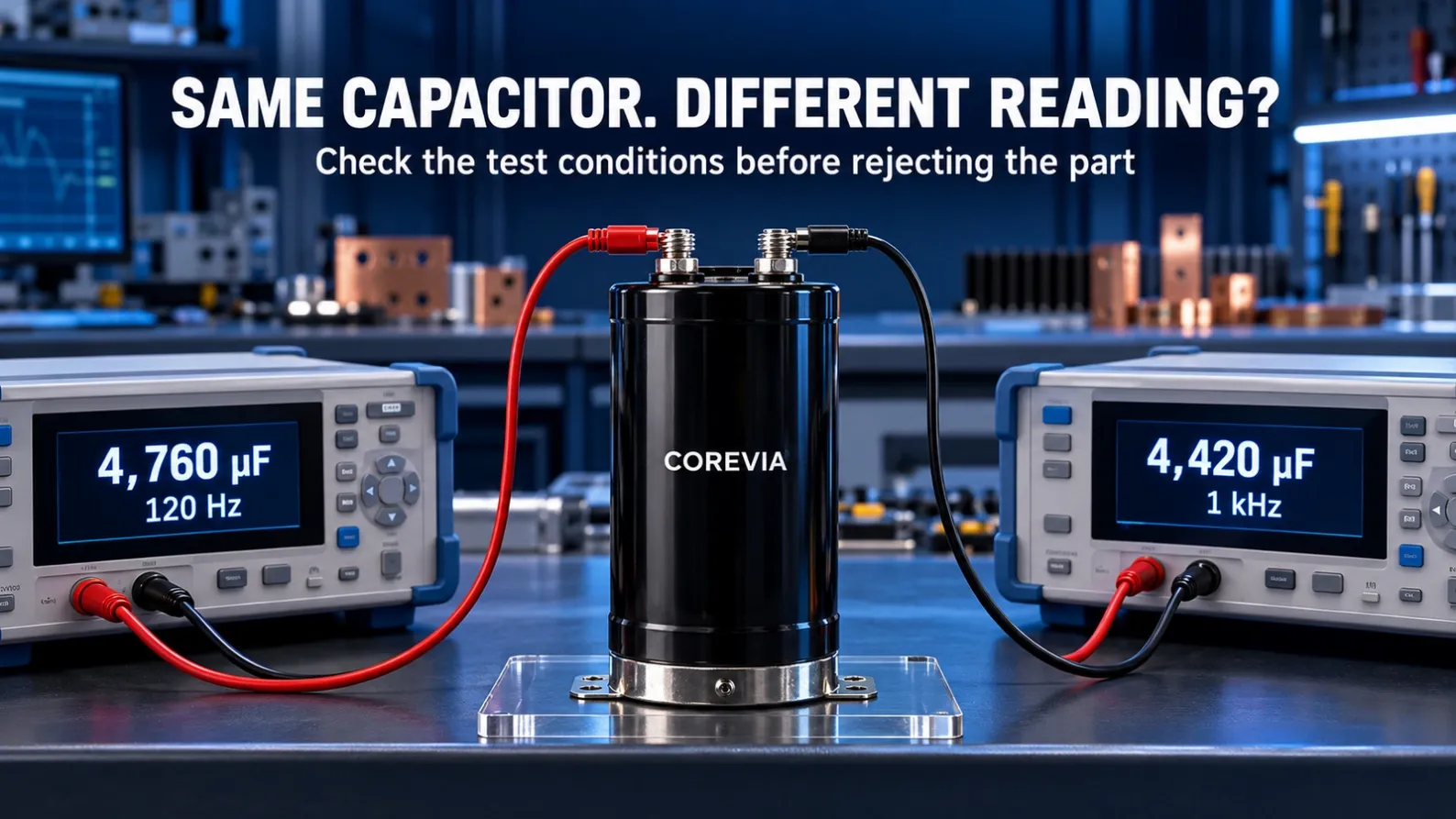
Two engineers test the same aluminum electrolytic capacitor.
One LCR meter shows 4,760 µF. Another shows 4,420 µF. The first reaction is often: one meter is wrong, or the capacitor is defective.
That conclusion may be too early.
Capacitance is not just a number printed on a screen. The reading depends on how the measurement was made. Before rejecting a large-can aluminum electrolytic capacitor, make sure both tests used the same conditions.
Why Test Frequency Changes the Reading
An aluminum electrolytic capacitor does not behave exactly the same at every test frequency. A measurement at 120 Hz cannot automatically be compared with one taken at 1 kHz.
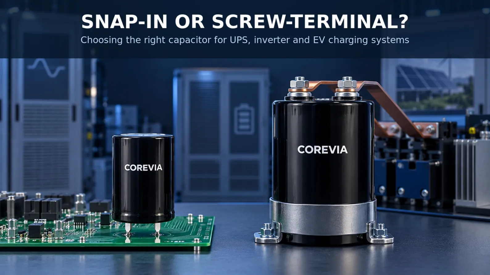
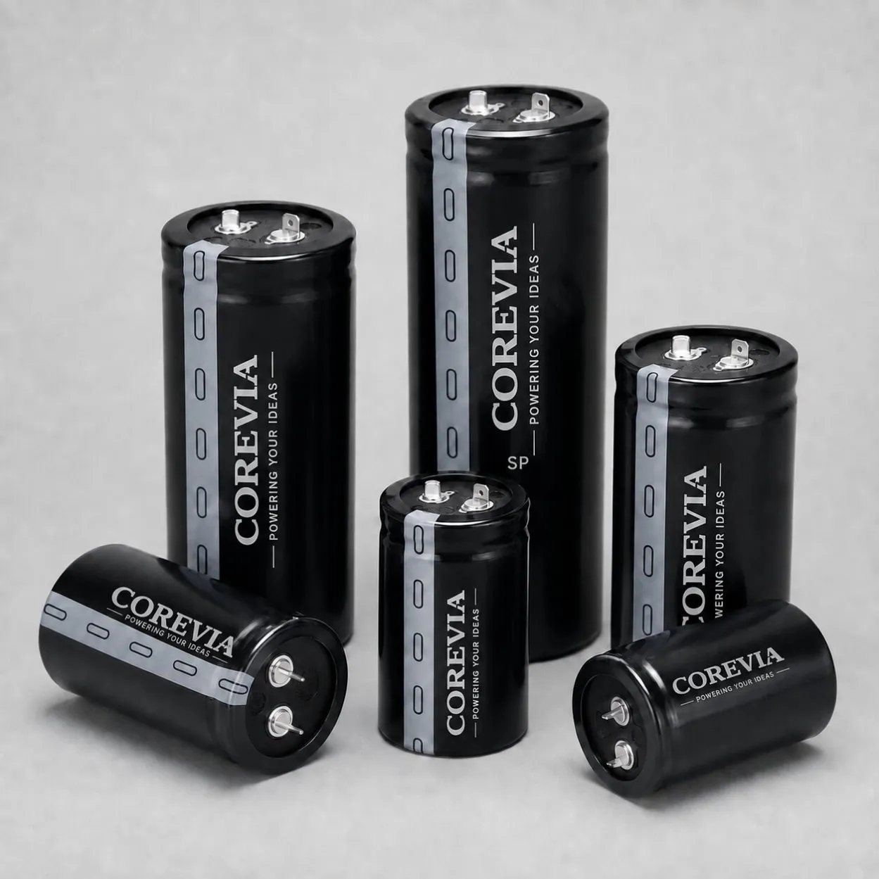
Many power-electronics applications use large snap-in or screw-terminal capacitors in the DC link. Their product specifications normally define a particular frequency and temperature for capacitance measurement. Always compare the result with the conditions stated for the exact capacitor series.
If a supplier, customer and third-party laboratory use different frequencies, they may report different values even when they are testing the same component.
Temperature Matters More Than Many People Expect
Capacitance measurement should also be made at a controlled and recorded temperature.
A capacitor taken from a cold warehouse may not give the same result as one that has stabilized in a warm laboratory. This is particularly important when a delivery arrives during winter or when the components have just been removed from operating equipment.
Allow the capacitor and the measuring equipment to reach a stable test temperature before making a final decision.
Check the LCR Meter Mode and Test Settings
Two LCR meters may use different default settings. Check the measurement mode, test signal level, range and calibration status.
Do not compare a quick handheld-meter result directly with a controlled incoming-inspection measurement unless the settings and methods are equivalent.
For repeatable capacitor testing, record:
• Instrument model and calibration status
• Test frequency
• Test signal level
• Measurement mode
• Capacitor temperature
• Connection method
• Time since discharge
Terminal Contact Can Create a False Reject
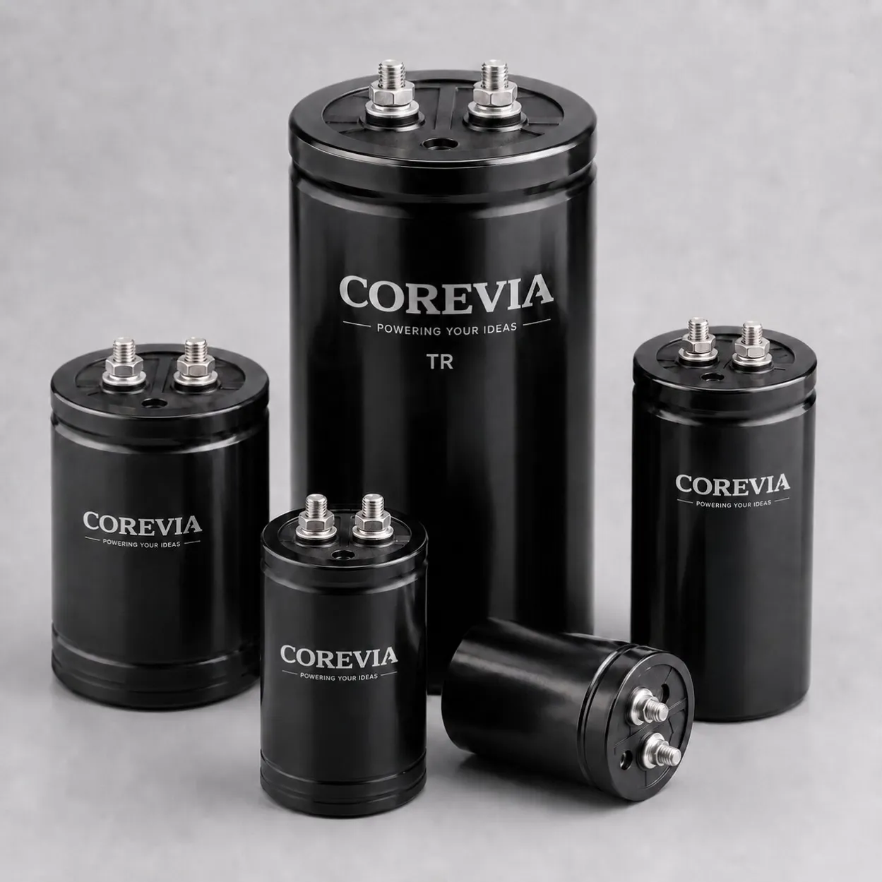
Connection quality is especially important for large screw-terminal aluminum electrolytic capacitors.
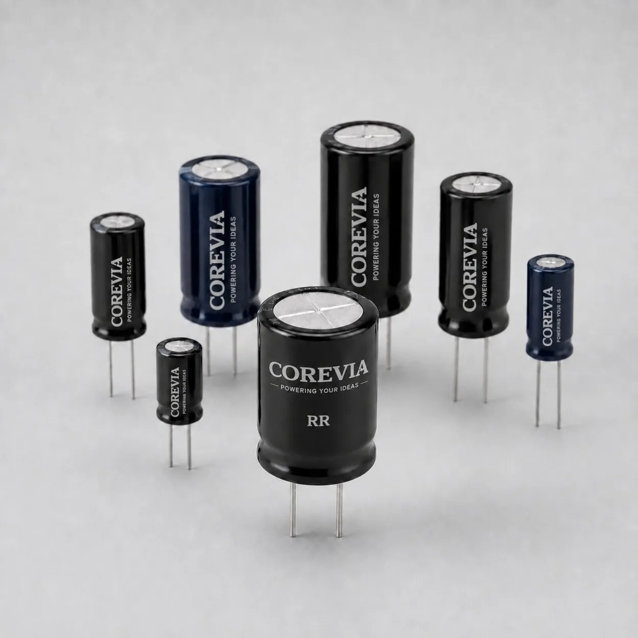
Oxidized terminals, loose clips, contact on a washer instead of the terminal surface, or long test leads can all affect the measurement. A test fixture that is suitable for a small radial capacitor may not be suitable for a high-capacitance screw-terminal capacitor.
Before blaming the component, clean the contact area if appropriate, use a stable fixture and repeat the test without moving the leads.
Discharge the Capacitor Safely Before Measurement
The equipment must be isolated from power, and the capacitor must be safely discharged before it is connected to a meter.
After discharge, follow a consistent waiting and measurement sequence. Testing one part immediately and another after a long delay makes the comparison less reliable.
Never short a charged high-capacitance capacitor directly with a tool. Use the equipment manufacturer's approved discharge procedure and verify the remaining voltage before handling.
A Practical Incoming-Inspection Checklist
When checking snap-in or screw-terminal aluminum electrolytic capacitors for UPS systems, inverters, EV chargers, industrial drives or energy-storage converters, use one documented method for every batch.
Confirm the exact capacitor model, rated voltage and capacitance.
Read the measurement conditions and tolerance in the correct datasheet.
Stabilize the capacitor at the specified test temperature.
Use the same calibrated meter, frequency, mode and fixture.
Discharge safely and follow the same waiting time.
Repeat the measurement to confirm that the result is stable.
Record the value together with the full test conditions.
When Should the Capacitor Be Rejected?
A different reading alone is not enough.
A capacitor should be assessed against the tolerance and test conditions specified for its exact series. If the result remains outside the permitted range after the measurement method has been verified, the part should be isolated for further review.
For field-return analysis, capacitance should not be considered by itself. Equipment history, operating voltage, loading, temperature, installation condition and visible damage can all help explain what happened.
Make the Test Repeatable Before Making It Expensive
Replacing a complete capacitor bank because two instruments produced different readings can waste time and money.
Start by making the test conditions clear and repeatable. A reliable measurement process helps purchasing teams, quality engineers and maintenance teams separate a genuine component problem from a test-method mismatch.
Related COREVIA resources:
Screw-terminal aluminum electrolytic capacitors:
https://www.coreviacap.com/products/screw-terminal-aluminum-electrolytic-capacitors
Snap-in aluminum electrolytic capacitors:
https://www.coreviacap.com/products/snap-in-terminal-aluminum-electrolytic-capacitors
Choosing capacitors for UPS, inverter and EV charging equipment:
https://www.coreviacap.com/posts/snap-in-vs-screw-terminal-capacitors-ups-inverter-ev-charger
Need help reviewing a measurement result?
Send COREVIA the capacitor model, datasheet, instrument model, test frequency, temperature and measured value. We can help determine whether the result indicates a real component problem or a difference in test conditions.
COREVIA — Aluminum Electrolytic Capacitor Solutions
Email
Website