Oct 18, 2026Reliability Engineering
Aluminum Electrolytic Capacitor Reverse Polarity: Checks Before Power-Up
Prevent reverse-polarity failures in UPS and inverter capacitor banks with practical wiring, polarity and pre-power-up verification checks.
Aluminum Electrolytic Capacitor Reverse Polarity: Checks Before Power-Up
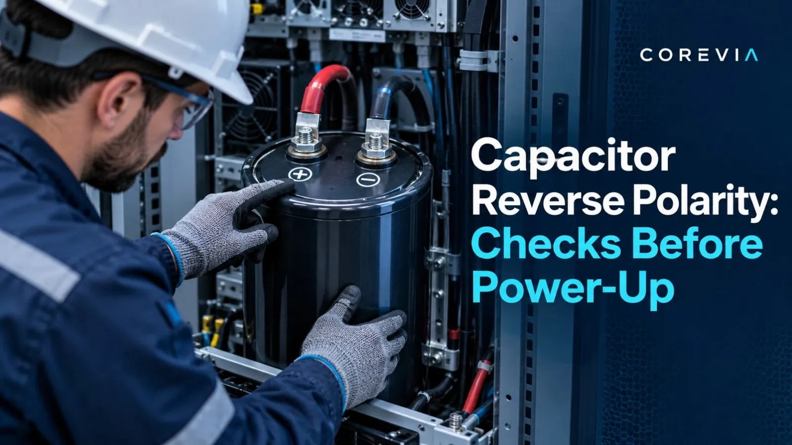
A polarized aluminum electrolytic capacitor is intended to operate with its positive terminal at a higher potential than its negative terminal. In a UPS, inverter or industrial power supply, a wiring error can put reverse voltage across the capacitor during the first start-up. The safest time to catch that error is before power is applied.
Reverse-polarity prevention is a circuit and assembly task, not just a visual check of the printed sleeve. The capacitor marking, terminal drawing, busbar layout, PCB legend and measured circuit polarity all need to agree.
Why reverse voltage is different from normal ripple
Normal ripple current rides on a DC bias; it does not mean the capacitor terminals may swap polarity. If the instantaneous voltage across a polarized capacitor crosses through zero and reverses, the application needs a separate design review. A normal polarized part is not made safe merely by choosing a higher DC voltage rating.
Aluminum electrolytic capacitors use an oxide dielectric formed on the anode foil. Under reverse bias, the opposite electrode does not provide equivalent voltage withstand. Current and heating can rise, sometimes at surprisingly low reverse voltage. The outcome depends on the voltage, duration, temperature and circuit energy: capacitance may deteriorate, the pressure relief may operate, or the part may fail open or short. Do not treat an apparent successful first power-up as proof that a reverse-biased part is acceptable.
Where polarity mistakes enter a build
In a screw-terminal bank, positive and negative terminals may be easy to identify on the component but harder to follow through a dense busbar assembly. A mirrored drawing, a rotated capacitor, an incorrectly labeled cable, or a last-minute harness change can defeat a simple color-code check. For snap-in and radial parts, footprint orientation and silkscreen markings can be reversed between the board view and the assembly view. A replacement part may also use a different terminal layout from the one assumed by the work instruction.
The risk is not limited to assembly mistakes. During power-down, regenerative operation, test sequences or an unusual fault, a circuit can behave differently from its steady-state schematic. The design engineer should confirm the actual voltage waveform across each capacitor under start-up, normal operation and shutdown, including relevant abnormal conditions.
A pre-power-up polarity verification sequence
• Identify the exact capacitor part number and check the manufacturer’s terminal or lead drawing. Do not infer polarity from a similar-looking series.
• Match the physical positive and negative marks to the approved assembly drawing and the PCB or busbar labels.
• Trace each connection to the intended DC-bus positive and negative nodes. Check both ends of cables and harnesses, not just the capacitor end.
• Compare the installed orientation with a known-good sample or an independently reviewed drawing. A second-person check is useful for the first article of a new build.
• With the equipment safely isolated and its stored energy discharged according to the approved procedure, perform the specified continuity and polarity checks using suitable test equipment.
• Before full energization, follow the equipment maker’s controlled commissioning procedure and verify the measured voltage polarity across the capacitor terminals. Only trained personnel should make live measurements.
• Record the inspection result and any discrepancy. Correct the drawing, label or assembly process before releasing the build.
Never rely on the capacitor’s pressure-relief vent as a protective device for a wiring error. The vent is a last-resort response to internal pressure, not an acceptable operating mode.
If reverse polarity may occur in the circuit
Do not solve a genuine polarity-reversal waveform by changing the installation orientation: the capacitor would then be wrong during another part of the cycle. Ask the design team to measure or simulate the terminal voltage and select a technology and circuit topology suitable for the actual waveform. Bipolar electrolytic, film or ceramic capacitors may be candidates depending on the voltage, capacitance, current and duty, but the entire application must be validated. “Bipolar” is not a blanket approval for continuous AC service.
What to do after a suspected reversal
Stop and isolate the equipment using the approved safety procedure. Do not touch the capacitor until stored energy has been safely discharged and verified. Record the wiring state, duration and magnitude of the event if known, and inspect for venting, leakage, swelling or discoloration. A part can be degraded without obvious external damage, so do not simply swap the leads and return it to service. Have a qualified engineer and the capacitor supplier decide whether replacement and further testing are required.
For COREVIA aluminum electrolytic capacitors, send the exact part number, terminal drawing, circuit schematic, expected voltage waveform and assembly photos to [email protected] for application review before production.
Technical references
Nichicon Application Guidelines for Aluminum Electrolytic Capacitors; Panasonic FAQ: failure modes under reverse voltage. Always follow the specification for the actual capacitor series and the equipment’s approved safety procedures.