Oct 14, 2026
Aluminum Electrolytic Capacitor Leakage Current Testing: Conditions, Limits and Acceptance
How leakage current is specified and tested for aluminum electrolytic capacitors: stabilization, the 0.01 CV limit, acceptance criteria and temperature correction.
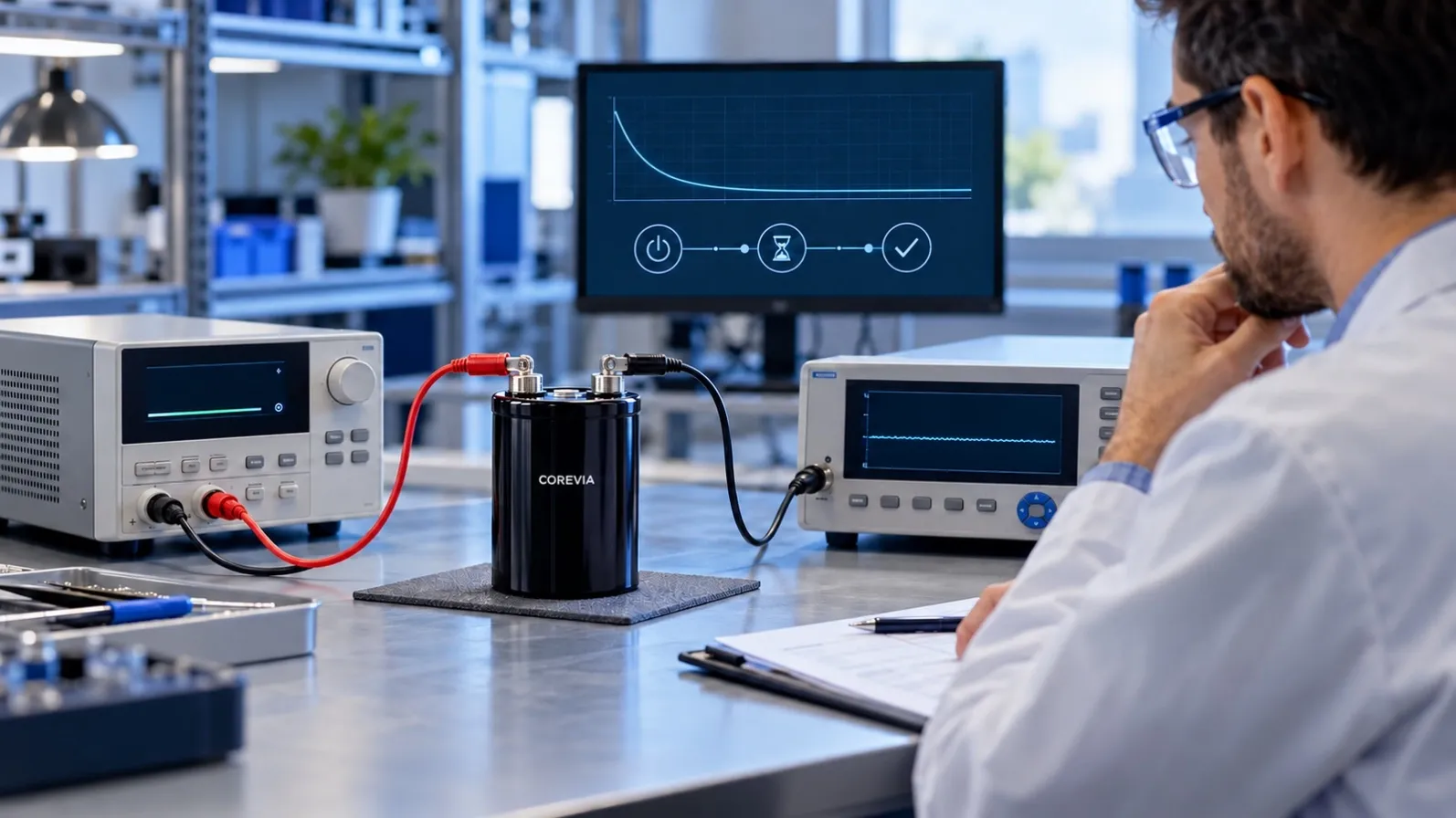
Leakage current is the small DC current that keeps flowing through an aluminum electrolytic capacitor after the applied voltage has stabilized. It is one of the first parameters a design engineer checks when qualifying a supplier, and one of the most common items on an incoming inspection report. This page explains how leakage current is specified for aluminum electrolytic capacitors, how the standard test is performed, how to work through the acceptance limits, and what information to provide when you ask a supplier to review an out-of-limit result.
What a Leakage Current Specification Actually Defines
Leakage current (often abbreviated DCL) is the current that flows through the dielectric aluminum oxide layer. A perfectly formed oxide would block DC almost completely; in practice, tiny imperfections, chloride contamination, and the natural quality of the oxide mean a small current always remains. The specification answers one question: how much DC current is acceptable through the dielectric when the rated voltage is applied under defined conditions?
Three points matter when reading the specification:
- The limit applies after a defined stabilization time at rated voltage, not at the moment of connection.
- The limit is stated at a defined temperature, normally 20 °C, and it rises sharply at low temperature and with long storage.
- Leakage current is not a fixed number for a series — it scales with capacitance and rated voltage.
Test Voltage, Temperature and Measurement Time
The industry-standard method, aligned with IEC 60384-4 and JIS C 5101-4, is straightforward:
- Applied voltage: the rated voltage of the capacitor (some specifications use an aged or derated voltage for measurement after endurance tests — always check which one your report uses).
- Temperature: 20 °C as the reference, with limits typically valid in the range of 5–35 °C unless otherwise stated.
- Measurement time: leakage is read after the voltage has been applied long enough for the charging and dielectric absorption currents to decay. Commonly 1 to 5 minutes depending on the specification — the time must be identical when you compare two readings.
If you compare a reading taken after 30 seconds with a limit defined at 3 minutes, the comparison is not valid. Record the elapsed time with every measurement.
Typical Limits and Worked Examples
Many aluminum electrolytic capacitor series define leakage current with a formula of the form:
DCL ≤ 0.01 × C × V (result in µA, with C in µF and V in volts), after the stated time at rated voltage and 20 °C. Low-leakage and specialty series may use tighter formulas or fixed maximum values — always confirm the exact statement on the datasheet revision you are qualifying against.
Two worked examples using this common formula:
- Small radial part, 100 µF / 25 V: 0.01 × 100 × 25 = 25 µA maximum after the specified time.
- Large screw terminal, 4,700 µF / 450 V: 0.01 × 4,700 × 450 = 21,150 µA ≈ 21 mA maximum after the specified time.
The second example illustrates why leakage current scales matter: 21 mA sounds large until you see that it is 0.01 CV for a 2,115 joule-scale part. Judge every reading against the limit calculated for that specific rating, never against a generic "small number".
Test Setup and Current Limiting
A proper bench setup protects both the measurement and the capacitor:
- Connect the capacitor with correct polarity to a DC supply set to rated voltage.
- Insert a current-limiting resistor (typically 1 kΩ to 5 kΩ) in series to control the inrush charge current at connection.
- Measure the stabilized current with a suitable ammeter or the voltage across a precision shunt, after the specified stabilization time.
- Record, together with the reading: the part number and lot code, applied voltage, elapsed time, ambient temperature, and the series resistor value.
Skipping the series resistor is the most common bench error: the initial charge current can trip the supply or damage the part, and the reading will not represent dielectric leakage at all.
Reviewing Out-of-Limit Results
An out-of-limit reading is not automatically a failed capacitor. Work through this order:
- Confirm the conditions. Was the full rated voltage applied for the full specified time at a reasonable temperature? Long storage without re-forming is the most frequent cause of elevated leakage — this is a known, recoverable condition (see our guide on storage, shelf life and re-forming).
- Exclude measurement artifacts. Reversed polarity, insufficient stabilization time, meter burden, surface leakage from flux residues, and comparing readings taken at different times are all common false failures.
- Re-form and re-measure. Where the manufacturer's procedure allows, applying rated voltage for an extended period lets the oxide self-heal. Leakage normally falls back within limits; a part that does not recover should be quarantined.
- Escalate with evidence. If readings remain out of limit after re-forming, collect the recorded conditions and contact the supplier for a joint review.
For the difference between leakage current behavior and other common measurement discrepancies, see our article on why two testers can read different values on the same capacitor.
Information to Provide for a Supplier Test Review
To let the manufacturer review an out-of-limit result efficiently, provide:
- Full part number, rated voltage and capacitance, and the lot code from the sleeve.
- The applied voltage, elapsed time before reading, and ambient temperature.
- The test circuit, including the series resistor value and the instrument used.
- The readings themselves, plus photos of the setup if the result is disputed.
- Storage and application history: how long the parts sat idle and at what conditions.
With these five items, most leakage questions are closed within one engineering exchange instead of weeks of email.
Leakage Current FAQ
Is leakage current the same as insulation resistance? They describe the same dielectric behavior in two forms. Insulation resistance is leakage expressed as MΩ·µF; converting between them at the same test voltage is valid.
Why is my leakage reading higher than the datasheet after storage? The oxide partially dissolves during long idle storage, so leakage rises until the part has been re-formed at rated voltage. This is expected behavior, not a defect — follow the re-forming procedure and re-measure.
Does leakage current change with temperature? Yes. The limit in the datasheet is defined at 20 °C. Leakage rises steeply at low temperature and also increases at elevated temperature; readings taken far from 20 °C must be corrected before comparison.
Can I use the same acceptance limit for all voltages in a series? No. The limit scales with capacitance and rated voltage. Calculate 0.01 CV (or the series-specific formula) for each rating you test.
Which standard defines the test? The method follows IEC 60384-4 and JIS C 5101-4; the exact stabilization time and limit formula are stated in each series datasheet. Confirm the datasheet revision before writing an incoming inspection specification.
Need a leakage current review for a specific COREVIA series? Send us the part number, the rated voltage, your test circuit and the readings — our application team will review the result against the series specification.