Oct 4, 2026Application Guides
Aluminum Electrolytic Capacitors at High Altitude: What to Check
Learn what engineers should check when inverters, UPS systems and energy-storage equipment use aluminum electrolytic capacitors at high altitude.
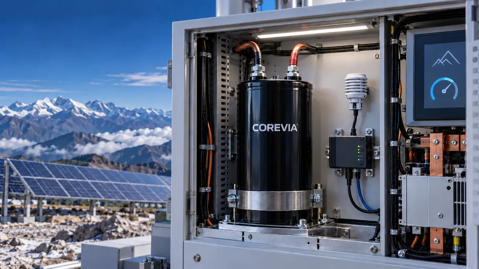
Learn what engineers should check when inverters, UPS systems and energy-storage equipment use aluminum electrolytic capacitors at high altitude.
Continue learning
Explore additional guidance on capacitor selection, operating conditions and reliability.
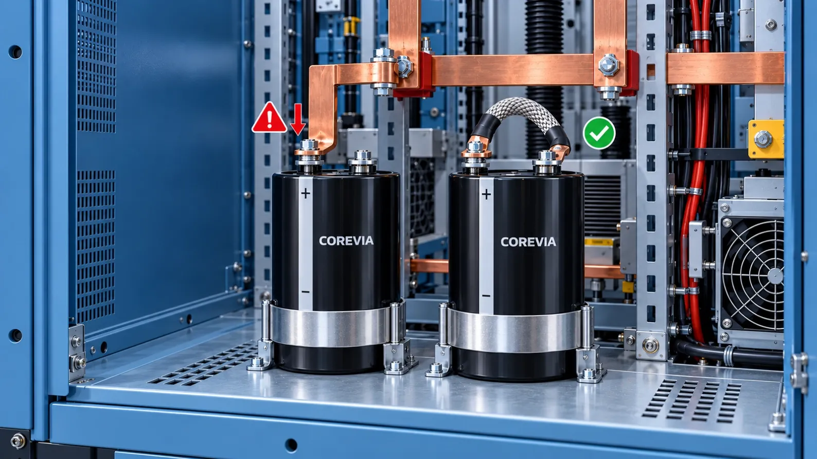
Learn how rigid busbars, heavy cables and poor alignment can stress screw-terminal aluminum electrolytic capacitors and cause unreliable connections.
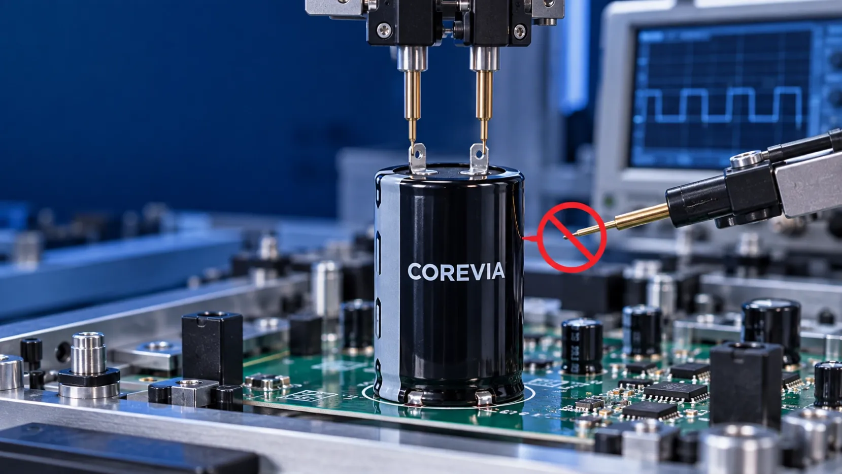
Learn why using an aluminum electrolytic capacitor can as an ICT electrode causes unstable readings and false PCB failures, and how to test correctly.
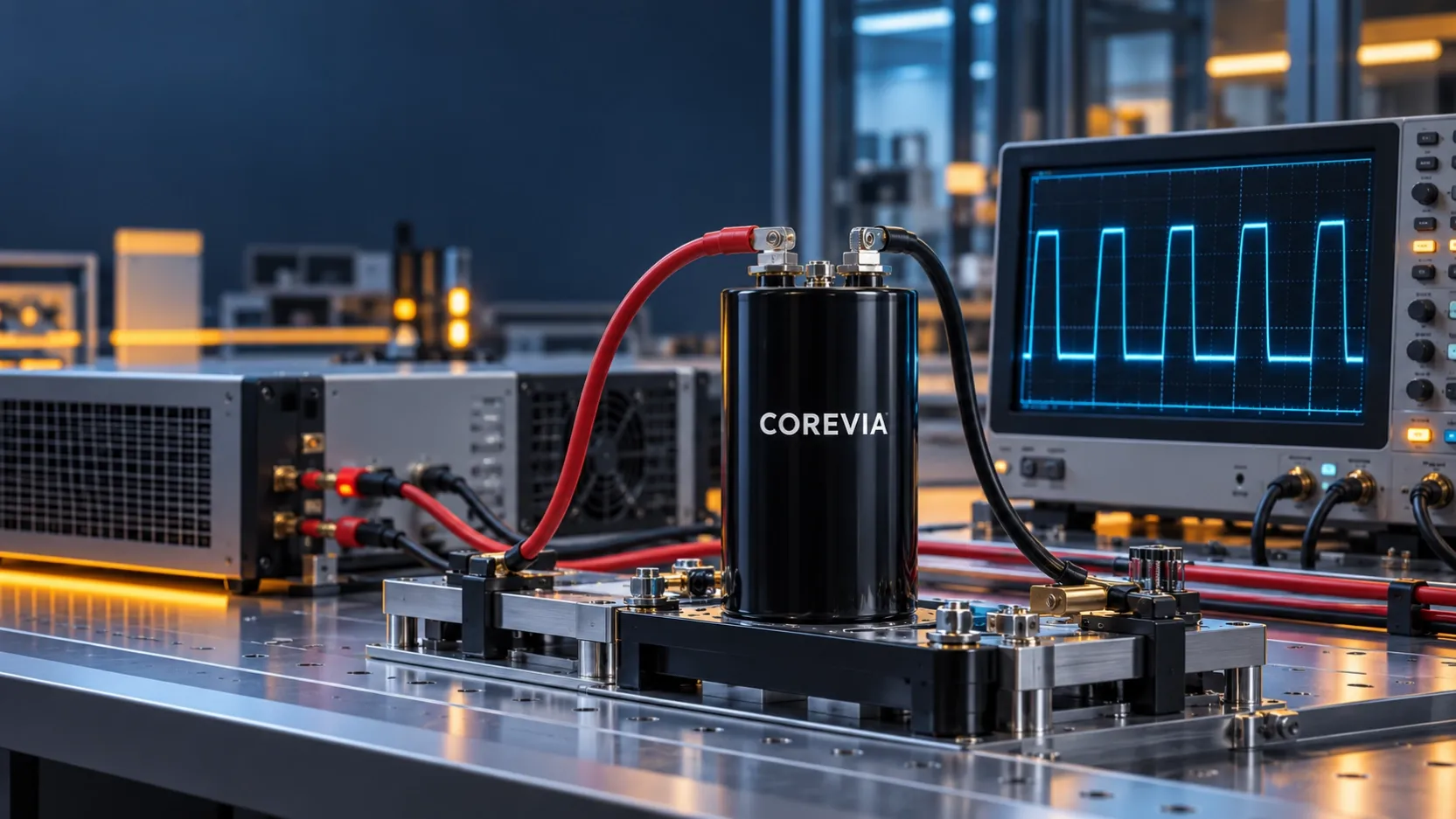
Learn why general-purpose aluminum electrolytic capacitors may not suit repeated rapid charge-discharge circuits and what operating data engineers should check.
Explore COREVIA Capacitor Families
Compare SMD, radial leaded, snap-in and screw terminal series. Check each series specification against your electrical, thermal and mechanical requirements.
Share voltage, capacitance, ripple current, dimensions and quantity for application-driven selection support.
Request a Quote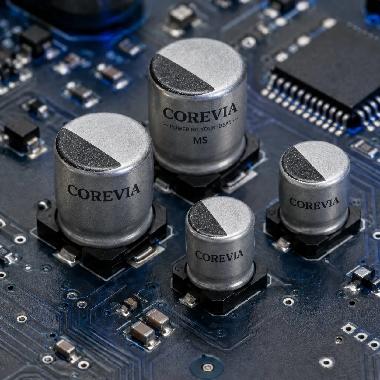
SMD aluminum electrolytic capacitors: MS, ML, MT, MZ and MM. Representative MS series: 6.3–50 V DC, 0.47–330 µF, −55 to +105 °C, 2,000-hour endurance.
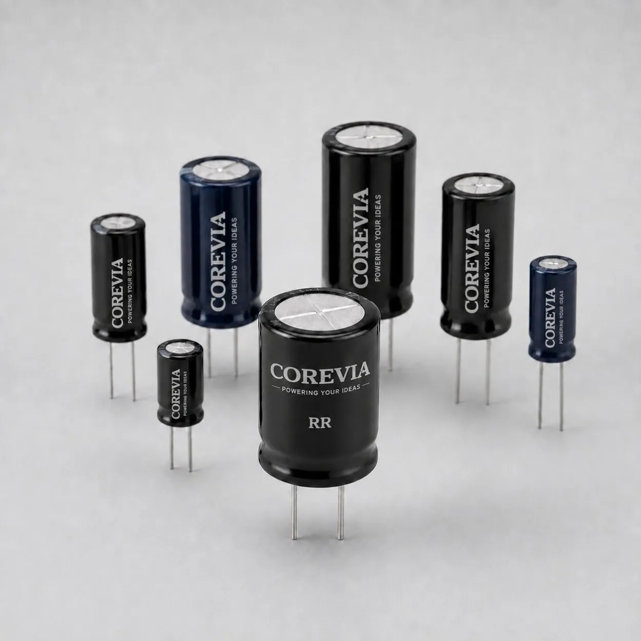
Radial Leaded capacitors: RR, RK, RH, RS, RG, RD, RF, RL, RT and RE. Representative RR: 0.1–15,000 µF and 2,000-hour endurance; see voltage-specific temperature ranges below.
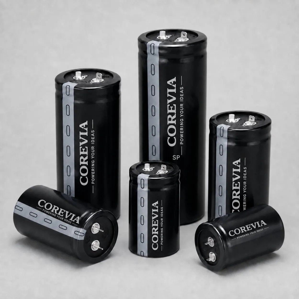
Snap-in capacitors: SP, SH, SS, SC, SF, SU, SD and SZ. Representative SP: 68–82,000 µF and 2,000-hour endurance; see voltage-specific temperature ranges below.
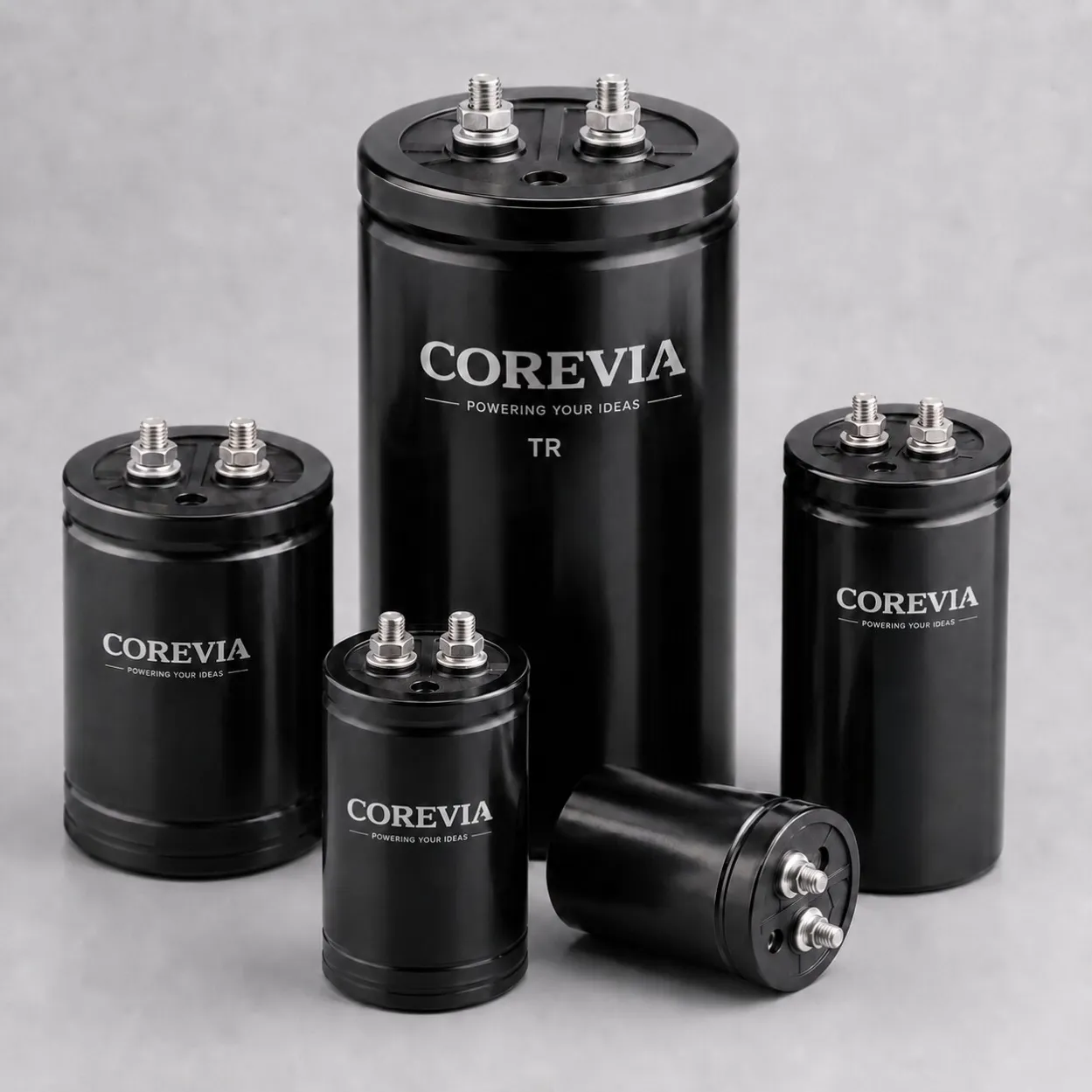
Screw Terminal capacitors: TR, TT, TX, TF, TK, TG, TN, TM, TD, TH and TA. Representative TR: 470–820,000 µF and 2,000-hour endurance; see voltage-specific temperature ranges below.